Microelectronics | CPLD Programmer
Synopsis
This is a parallel port programmer circuit for Xilinx XC9536 and XC9572 CPLDs. I use these frequently in my high-complexity digital projects.
Schematic Diagram
Let's take a look at the electrical schematic diagram. Just please (sic!) don't question my weird choice for the RJ-11 power connector.

Fig. 1: Electrical Principial Schematic

Fig. 2: Top Layer Printed Circuit Board

Fig. 3: Bottom Layer Printed Circuit Board
This schematic diagram was published within various Xilinx CPLD datasheets. It is not mine, and I didn't modify anything. The drawing is mine, though. Also the circuit layout is of my own design.
Construction and Pictures
While this is a simple circuit, I still added some pictures for future references.
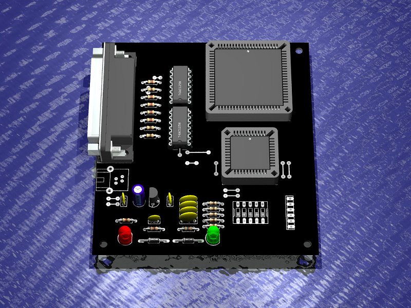
This is a graphical computer simulation of the PCB assembly.
Later edit: I think the raytracing software program was called POV-Ray, but I can't remember how I managed to connect it to EAGLE back in 2008. However, for those early times, I've found it impressive. These days (mid-2026), 3D electronics simulation programs are exceptionally capable. But somehow I don't need them anymore. I've seen and designed so many circuit boards that I can picture them in real-time inside my mind.
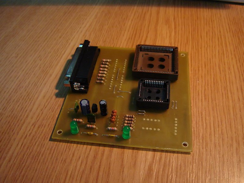
This is the completed PCB assembly. I still have to solder the line buffers.
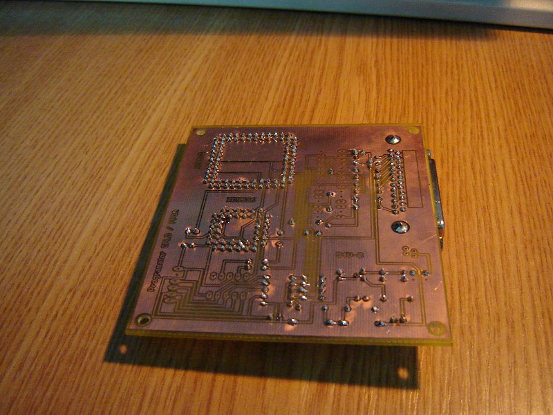
And the solder side.
Thank you for reading this page, and I hope you found it useful.
Copyright © 2004- Alexandru Groza
All rights reserved.
VER. 1.0 | REV. A