Microelectronics | Digital Tachometer
Synopsis
The Rostov 105 S-1 reel to reel tape deck is equipped with a mechanical tape counter. Since I wanted to enhance it, I decided to build a 4-digit 7-segment electronic tachometer. Later on, I acquire a second tape machine, this time a classic Rostov 105. Thus, I designed a second version of the tachometer.
The tachometer can count ascending or descending. In addition, it is resettable. Count pulses are fed to pin #4 of the microcontroller, on the rising edge. These pulses come from an IR barrier, constructed around an IR emitter and a matching phototransistor as a receiver. This assembly is installed behind the take-up reel hub. The optoelectronic assembly comes from a donor Rostov 105 tape deck.
The PLAY and REVERSE signals are collected from the logic command PCB assembly of the tape deck. For more details, refer to the command circuit schematic diagram. You can quickly figure out which NAND gate outputs (CD4011 equivalent ICs) are responsible for these signals.
Initially, I've implemented the tachometer with the PIC16F84A microcontroller in mind. But then I've quickly decided that PIC16F628A is a better alternative. I've used a software multiplexing technique to light up the 7-segment elements.
Schematic Diagram
First of all, let's check the electrical schematic diagram of the electronic tape counter.

Fig. 1: Core Electrical Schematic Diagram
The core of the schematic is the PIC16F628 microcontroller. This is being seconded by a pulse shaping circuit, built around a CD4093 (KR1561TL1) integrated circuit. TTL-compatible +5 V command voltages are generated by simple resistive dividers and KT315B transistors. I went with this approach to convert the +9 V command voltages commonly used by the CMOS circuits on the command PCB assembly, to TTL-compatible inputs for the PIC microcontroller.
The REWIND signal is negated, thus I wanted to make it active on the rising edge, via a simple KT315B transistor inverter. Of course, this could've been done in software, anyway. But let's go the hardware way for this design.
As a side note, KT315B transistors are equivalent to BC107A.

Fig. 2: Display Module Electrical Schematic Diagram
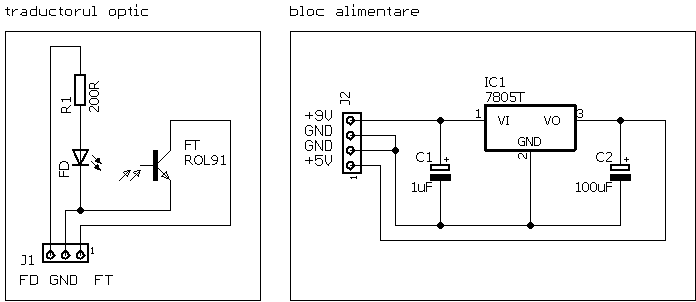
Fig. 3: Power Supply and Optoelectronic Barrier Electrical Schematic Diagram
In order to power up the electronic tape counter, a +5 V voltage is required. This is not naturally present anywhere in the tape recorder. I'll generate it via a simple linear voltage regulator of type LM7805, mounted on a small heat sink. In addition, the diagram above also shows how to connect the optical IR barrier emitter and receiver. You can build this yourself, or use a readily made module from a parts donor tape machine. I went the easy way and used one ready made. For sure, this step can be skipped and the pulses can simply be collected from the command PCB assembly, directly, via voltage dividers. But for this implementation, I went with the way I described above.
Software
I also release the software that runs inside the PIC microcontroller to power up the tachometer. However, this software can only be used with this specific schematic diagram revision and circuit board version, as it is not a generic counter program. Given the topology of the schematics and the 7-segment display connections, this software program will not work with the V2 schematic that is presented later on in this article.
To download the software, click the name of the file listed below. The .zip archive contains the required .hex file. Any programmer can be used, provided that it supports the PIC16F628(A) microcontroller.
- tahograf_v1.zip (archived
.hexfile)
Construction and Pictures
Here are a few pictures that depict various construction steps.
The red Hewlett-Packard 7-segment displays, are of common cathode type.

This is a simulation of what the PCB assembly will look like. Sometimes, I print (both sides) of a circuit board to a 1:1 scale.

Bottom side printed circuit board, home-made.

And the top side of the same PCB.

The resistors, transistors, and ceramic capacitor are all installed. The IC sockets are temporary, and are not soldered at this point. I will replace them with machine sockets.

Both PCBs are populated with parts.

And this is where the control PCB is going to be installed. The display PCB assembly, naturally, is going to be installed in place of the old mechanical tachometer.

And the connection cables between the display and the control PCBs are all sewn as a single thick bus. This construction closely mimics the factory way of binding wires together.

Various tests, and debugging of the software embedded in the MCU ROM.

The Rostov 105 S-1 with the front plate installed and the electronic tape counter, clearly speaks that it's ready for work.

And a (mandatory) night time picture.

After evaluating this project for a few months, I can clearly say that it works as expected.
Continuation
After the success of the first version, invariably came an update. Version 2 is going to be installed in my second Rostov reel to reel tape deck, this time a classic 105 model. There are slight improvements to the electrical schematic diagrams, and the software was updated to account for the new 7-segment driving method. This time, I wanted the counter to simply count seconds, instead of reel turns. And that's exactly what I programmed the software to do. However, by having a simplistic single IR barrier input, I cannot do a full fast forward or reverse counting of seconds. For that to happen, two IR barriers are needed, and the software becomes way more complex.
Schematic Diagram
Let's take a look at the new revision of the schematic diagram.

Fig. 1: Core Electrical Schematic Diagram
Followed by the display circuit.

Fig. 2: Display Module Electrical Schematic Diagram
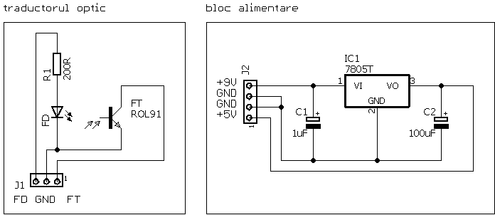
Fig. 3: Optoelectronic Barrier Electrical Schematic Diagram
This time, I went with a miniature linear voltage regulator in TO-92 package. Tests revealed that it barely gets warm to the touch.
Software
The software works only with the PIC16F628(A) microcontroller, and this specific revision of the schematic diagram.
To download the software, click the name of the file listed below. The .zip archive contains the required .hex file. Any programmer can be used, provided that it supports the PIC16F628(A) microcontroller.
- tahograf_v2.zip (archived
.hexfile)
Construction and Pictures
Following, are a few pictures with the second electronic tape counter.
This time, the PCB is single-layer, and the 7-segment elements are green.

This is the solder side.

A detailed view of the 7-segment green elements, and the four driver transistors. Driving 7-segment elements with individual transistors is the way to go, if you want reliability in time, and you want to protect the PIC internal output drivers.

Next follows the Reed relay.

I installed the hex nuts and added the connection cables.

I am going to saw them in a bus.

Like this. I really like this method as it's fast and looks very factory-like.

This is the single-layer PCB for the command circuit.

Next, I soldered all electronic components.

And this is the solder side.

Finally, I installed the integrated circuits.

And these are the solder points where I collect the command signals for the REWIND (red wire) and PLAY (brown wire) signals.

The Rostov 105 reel to reel tape deck, with the green tape counter installed.

Both Rostov 105 machines, with their counters running.

Conclusions
Honestly I don't like the way the PCBs look like. I've made them via toner-transfer method, using a hot iron. While functional, they look very amateurish I'm sure I could perfect this technique, but on the other side, I'm mostly done with home-made PCBs. I've been making them since the early 90s, and now I consider it's time to move to industrially built PCBs.
A third version will follow soon, as I can already see improvements to this design. I plan a simpler hardware interface, and an updated software package. At this point, I am not sure I want to continue this project. But time will tell.
Thank you for reading this page, and I hope you found it useful, either in its current form, or as a base for a new project. Or even as educational material.
Copyright © 2004- Alexandru Groza
All rights reserved.
VER. 1.0 | REV. A