Microelectronics | Dynamic Light
Synopsis
Looking through my spare parts, I've found a box of CDB4xx TTL logic ICs. They are all new, as in never used, but were produced in the 1980s. I said to myself, I should put them to good use, somehow. Then, I remembered that back in the mid-1990s, I've stumbled upon an issue of the Tehnium magazine that featured a dynamic light circuit. Thus, I've found the article that presented the schematic designed by Ioan Aldea and Constantin Cojan (YO6OAE). Immediately I wanted to try it.
I've scanned the original article text and schematic. While the text is in Romanian, the schematic is universal, and it's easily understood. Truth tables are also given by the authors.
Schematic Diagram
Here is the original article that I've scanned back in 2002.
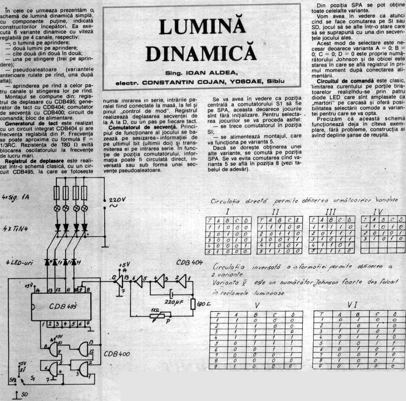
As the authors say, the circuit is easy to build, and works first try, giving instant satisfaction. In addition, it's a fun circuit to build for beginners.
Construction and Pictures
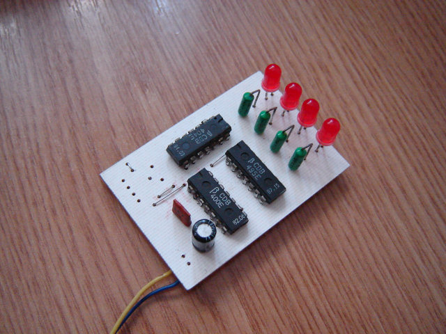
Here are some pictures of the assembled circuit.
This is a view of the component side. There are some unpopulated holes on the PCB. These are for the variable resistor that adjusts the speed of the oscillator. There is also the unpopulated pin header that allows cycling through the dynamic lighting modes.
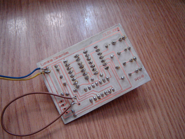
Here is a view of the solder side. The brown wire is a wire bodge, for testing purposes. Normally, these are the pins for the variable resistor.
It's interesting how with only three ICs you can achieve a dynamic light with so many display modes. I do agree that this circuit is a good starting point for those who want to experiment with logic ICs and learn how they work. Also you can visualize how the combined individual IC truth tables translate together into the whole circuit operation.
Thank you for reading this page, and I hope you found it useful.
Copyright © 2004- Alexandru Groza
All rights reserved.
VER. 1.0 | REV. A