Microelectronics | Stereo Buffer
Synopsis
I decided to build this stereo audio buffer since I had a few AC127 Germanium transistors available in my parts box. As there is very little use for such old transistors, I designed a small schematic diagram that depicts a classic audio amplification stage. Considering the simplicity of this design, one might replicate it with different transistors, be them germanium or silicon types. In any case, the static operating point of operation for the transistors has to be recalculated.
To push things further, I chose to make a rectifying bridge with germanium diodes of type EFD108 (or EFD109). Nonetheless, this is totally unconventional, but I like to experiment with electronics. A series stabilizer is used to smooth out the output of the power supply. This is based on two AC185 germanium transistors. The current consumption of the circuit is negligible, thus there's no need for heat sinks. And the diodes will be holding up just fine.
The mains power transformer was designed to have two secondary windings. The first winding outputs 4 V / 300 mA and is solely used for the power-on indicator (a standard incandescent bulb rated at 6.3 V / 220 mA). It's clear that the bulb is undervolted, but that's deliberate as it will extend its life practically forever. The other secondary winding outputs 8 V / 300 mA and is used for powering the circuit.
Schematic Diagram
Let's start by taking a look at the schematic diagram.

Fig. 1: Electrical Schematic Diagram

Fig. 2: Bottom Layer Printed Circuit Board
Files
In case you'd like to build this project using DIY methods, the PDF file contains the 1:1 mirrored circuit layout.
- stbuf-bottom.pdf (mirrored circuit layout)
Construction and Pictures
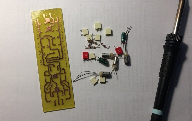
The DIY printed circuit board, and a few of the electronic components that will be part of the assembly.
Copyright © 2004- Alexandru Groza
All rights reserved.
VER. 1.0 | REV. A