Microelectronics | Microcalculator Zeta V2
Synopsis
This is one of Sergey Kiselev's projects that I wanted to build for some time. You can find the official project documentation on the Zeta SBC V2 Internet page.
After a brief talk with Sergey and a friend of his, Todd Goodman, I've finally decided to build the project myself. So I have bought some PCBs designed by Sergey. Here are a few details about the components and features involved in this project.
- Z80 CPU
- Z80 CTC
- 16550 UART
- 8255 PPI
- Western Digital WD37C65 FDC
- 512 K RAM (battery backed, non-volatile)
- 512 K ROM
- Dallas DS1302 RTC
I liked the idea of having CP/M directly in ROM. For a long time I've been longing to try out CP/M. Back in 2009, I've designed a Z80-based microcomputer, but based on an own architectural idea, totally non-compatible with standard ROMs or even CP/M. In addition, I had to program the firmware myself, which lead to a long development cycle, errors, debugging, reverse engineering, and frustration.
On the other hand, the Zeta SBC V2 implements a clean, simple to understand architecture. The quality of the industrially built PCBs is outstanding. The electronic components number is relatively low, and the system is easily interfaced to a standard 3½ floppy disk drive. In addition, it can also be connected to an IDE hard disk drive, by means of a simple adapter based on inverter gates.
Not to mention there is also the extension PCB for video signal and SD card for mass storage. As soon as I saw that, I knew I had to build one.
In time, I'd like to (maybe) add some personal touches to the software. Initially, I'd like to create a few add on programs to extend CP/M's functionality. Later on, I might use the Zeta computer to control a Nixie clock, or maybe even for Morse code encoding/decoding for my HAM radio activities. But for now, I don't have a clear path to follow.
Construction and Pictures
Since I have nothing to do with the design of this project, neither schematic diagram-level nor circuit layout, I will just add some pictures that I took during the construction of this Z80-based computer. I have used integrated circuits from the 74LS series for command logic, and CMOS ICs for the rest of the system. I am looking forward to a low energy consumption as I plan to leave the computer on practically forever, doing repetitive tasks (maybe even reading GPS time from a GPS receiver; as I said, I have a few ideas). I plan to power the computer from my Z80 Microcomputer Power Supply.
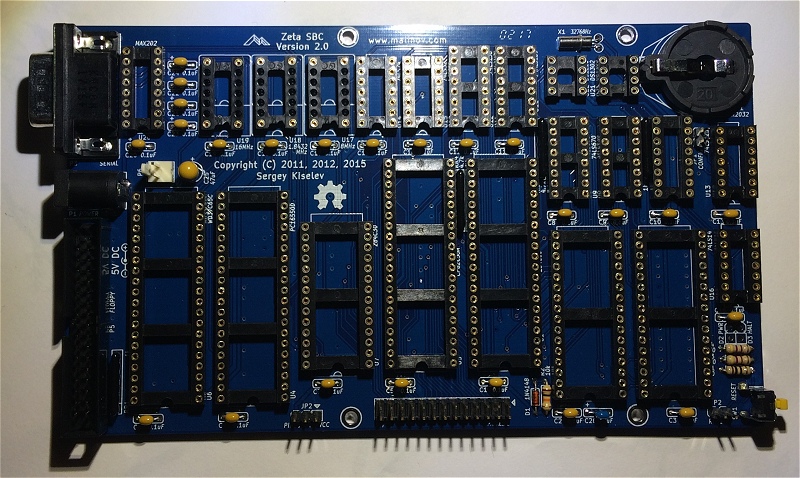
The mainboard printed circuit board, top layer.

Sergey conveniently designed this PCB so that the serial port, power, and floppy disk drive connectors are on one edge of the board.
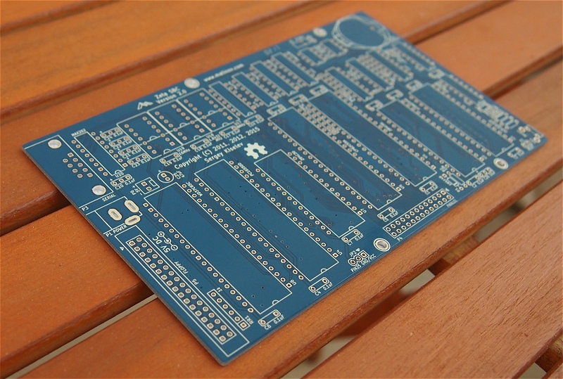
However, the reset button and the operation LEDs are on the other side of the PCB. There wasn't enough space near the connectors anyway.
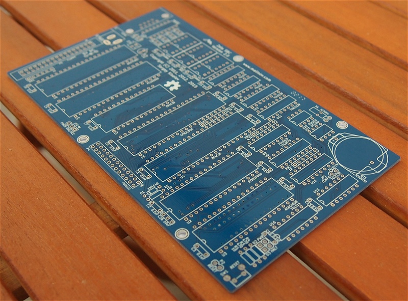
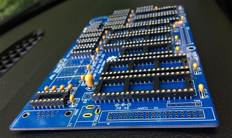
I've soldered most of the precision machine sockets and a few passive components.
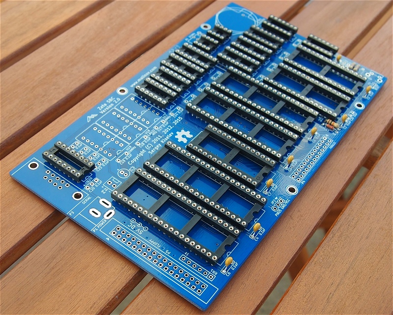
More MLCC and tantalum capacitors found their way already.
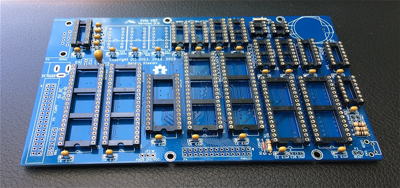
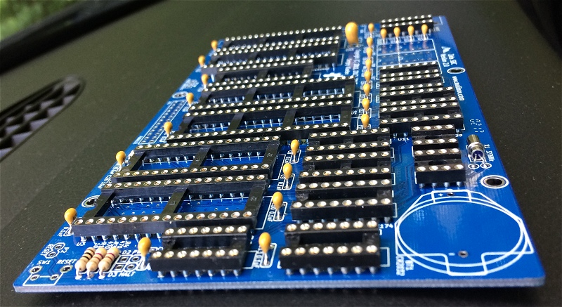
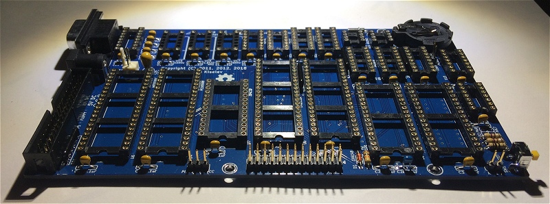
Let's see the PCB from a different angle.
And an opposite-angle view.
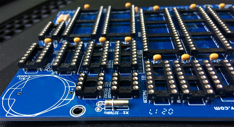
Here is the small 32,768 kHz quartz crustal for the real-time clock.
I like the yellow-blue contrast.
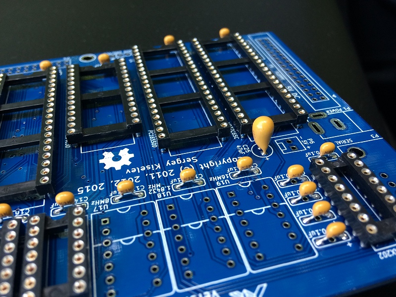
The three missing components are quartz oscillators. According to the silkscreen, this printed circuit board was made in February 2017.
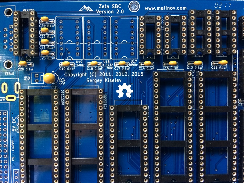
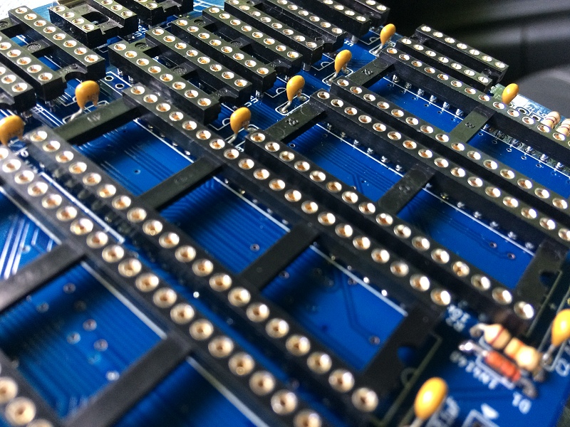
A detailed view of the precision machine sockets.
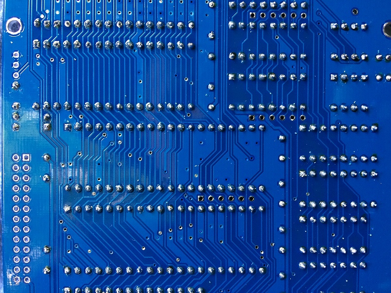
And a detailed view of the solder side.
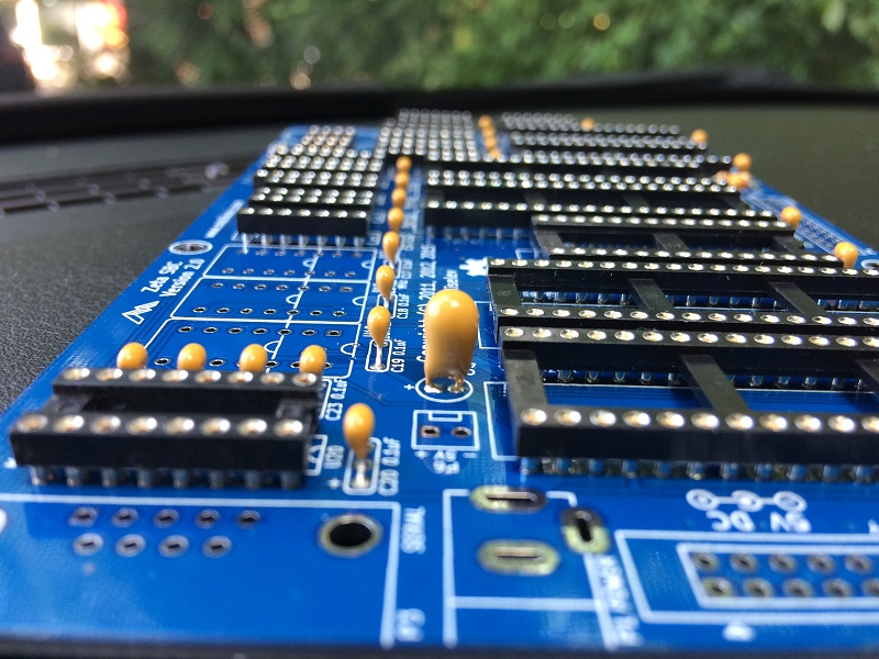
The big tantalum capacitor in the center is a local power supply ripple filter.
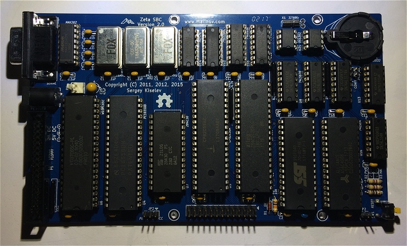
Eventually, I have soldered all components.
I like the overall monochromatic three-tone color theme of the finished system.
I have recovered these FOX branded quartz oscillators in 1998 from an old Zenith mainboard based on the 80286 CPU running at 10 MHz (NEAT chipset).
And finally, I have inserted all integrated circuits in their respective sockets.
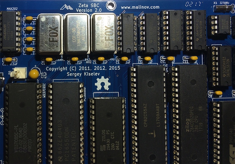
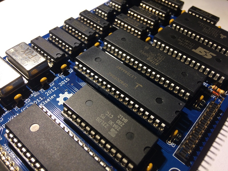
Here is a detailed view of the Z80 CPU and various peripherals.
Now follows the printed circuit board for the VGA signal generator, PS/2 keyboard, and second serial port.
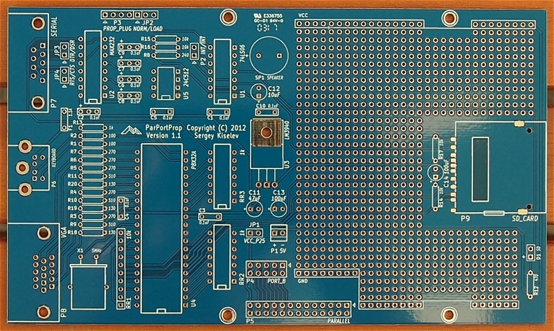
The SD card access LED is aligned with the power and halt LEDs on the mainboard.
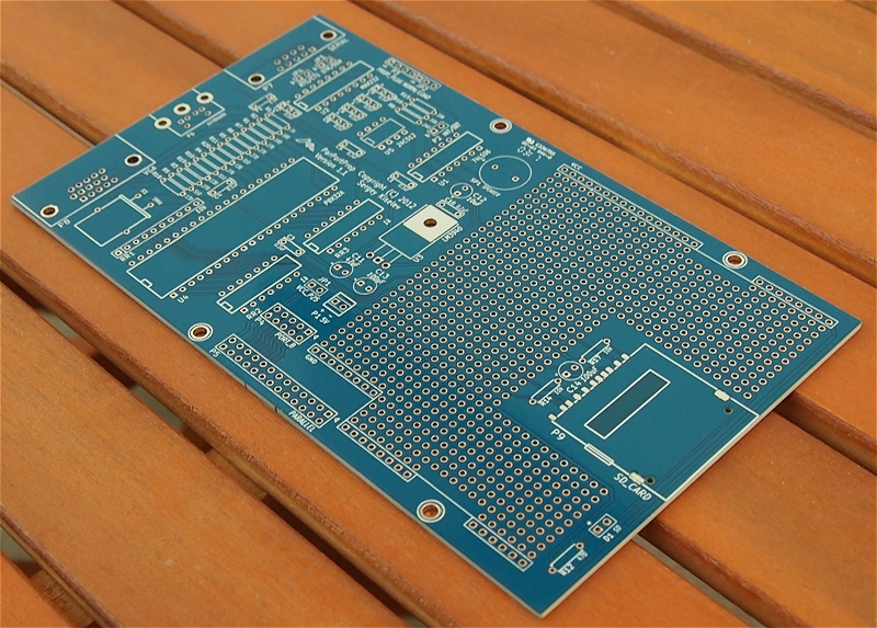
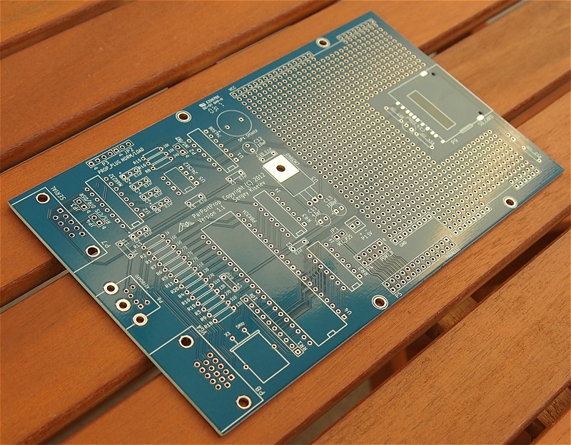
While the second serial port, PS/2 keyboard, and VGA connectors are on matching edge of the card to align with the connectors on the mainboard.
I have mounted the mainboard over the peripheral PCB with hexagonal spacers. And I have prepared an old 1,440 K Sony floppy disk drive.
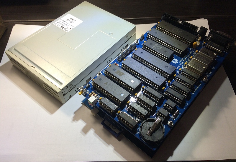
I like how the connectors align between the two PCB assemblies.
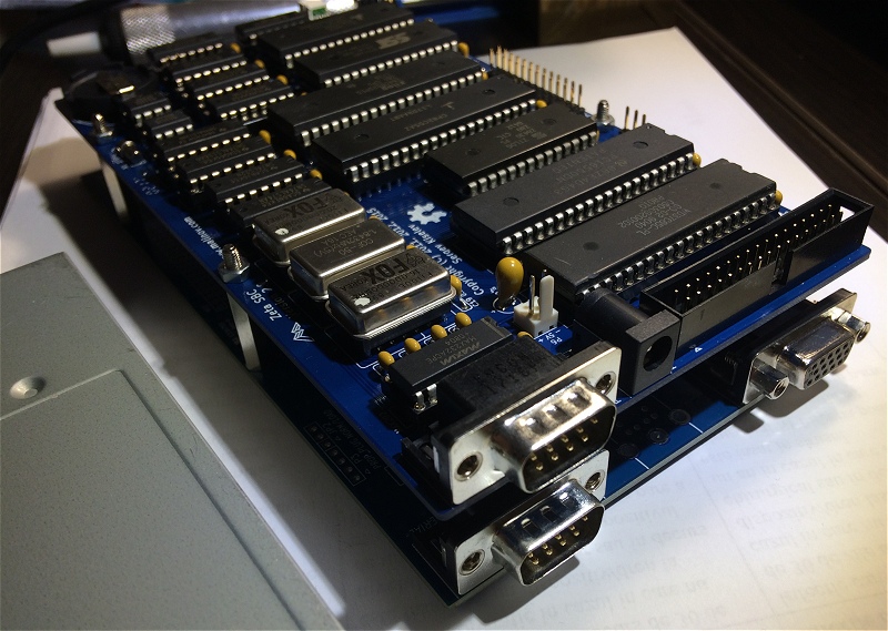
The same for the LEDs. I've searched for these kinds of LEDs for a long time. I've seen them used in industrial equipment from the 1980s and 1990s. There was even a Miniscribe 8425 hard disk drive that used a red LED of the same type.
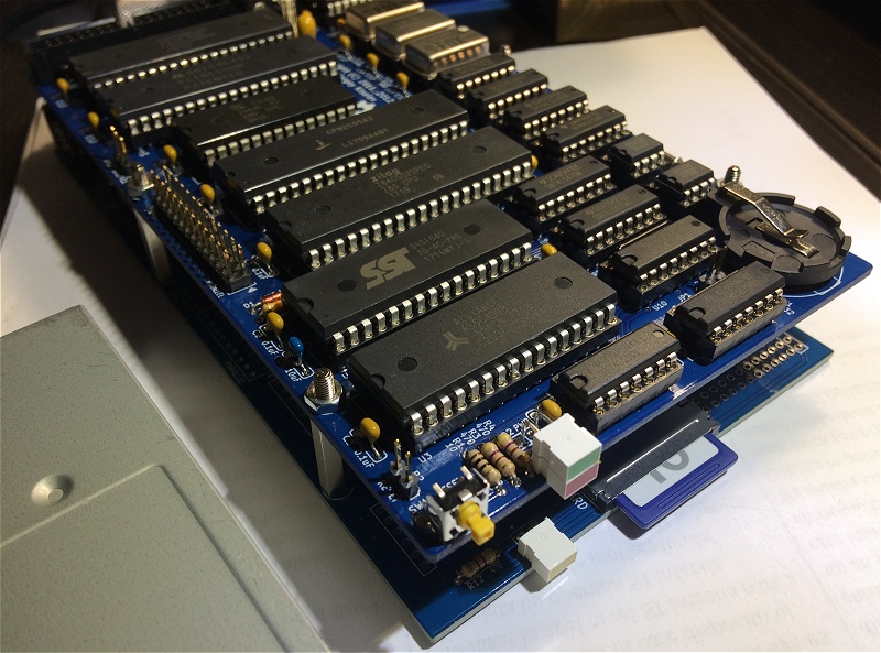
I like this project a lot and I had fun while building it. Big thanks to both Sergey and Todd for their help.
Thank you for reading this page, and I hope you found it useful.
Copyright © 2004- Alexandru Groza
All rights reserved.
VER. 1.0 | REV. A