Microelectronics | Symmetricom TrueTime NTS-100
Synopsis
This is an odd piece of equipment, rarely seen in operation these days. It is a network time server that supports NTP, and is able to constantly monitor GPS satellites to obtain a 10 microsecond precision time stamp, as advertised. Since it's a server, it has its own IP address and is able to respond to multiple devices constantly querying the time. Wait, isn't that something that already exists on the Internet? Yes, for sure, there are many public NTP servers, but there's a catch: Internet access is required. A local NTP server doesn't rely on the Internet, and it fits all of my use-cases.
I won't be detailing here all my networked devices that don't have Internet access, but still require accurate time synchronization, but I can name a few. For instance, there are two file servers, one main and the other one an exact backup copy of the main server, both running TrueNAS Core, and are not connected to the Internet. rsync really requires accurate time stamps for backups. Then there are two terminals that only have access to the main file server. And there are my DIY retro computers running MS-DOS -- these are quasi connected to the Internet. In some cases, while playing Wolfenstein 3-D, the system time drifts, thus manual reentry of time is required afterward. With the local NTP server, this behavior can be automated. Is time and date really necessary in MS-DOS? Well, yes, if you do computer programming and use any kind of source code control.
I recently bought this network time server off eBay, advertised as fully working. And so it was, up until it broke, almost a full week after it was connected to my local network. One morning, I heard a high-pitched electrical noise coming from my office. I went to investigate, and the source of the sound was the TrueTime NTS-100. Oh, well! I looked at the LCD, and it was completely off, no backlight, and no text.
Disclaimer
This article is not to be treated as a do-it-yourself tutorial on how to fix, restore, rebuild, or improve this unit. This was not my initial intention. But you can consider this whole content as a general guideline, should you decide to attempt any service procedure on an identical or similar unit.
The entire documentation is just a reflection of my work and I cannot be held responsible if you damage your unit, or even harm yourself in the process.
Implementation Analysis
The TrueTime NTS-100 device was designed and built by a company called Symmetricom in the U.S.A. during the mid to late 1990s. While functionality-wise fairly complex, the hardware implementation is minimalist. It is obvious that these people knew their business well. But back in 2013, Symmetricom, Inc. was bought by Microsemi. Which in turn, was bought by Microchip in 2018. So it's safe to assume they might still be around, in one form or another. But rest assured, even their older products were state of the art.
This unit effectively implements a Stratum 1 network time server that gets the real-time clock data from Stratum 0 sources, in this case GPS satellites.
The construction is fairly simple, and inside there are only three main printed circuit boards, and a handful of other support PCBs and circuitry. The main functional blocks implement the power supply, the GPS receiver, and the core computer. The rest are peripherals such as an LCD with its controller PCB and the input keyboard.
The LCD has a parallel communications interface, and the keyboard is scanned as a matrix, connected the the computer board by means of a 10-wire flat ribbon cable.
Power Supply
The unit is powered by a switching mode power supply. The design appears to be very robust, but the printed circuit board assembly is most probably a built-to-order unit. There is a Computer ProductsTM Power Conversion sticker on the HF transformer. So, even if the PCB is not of US provenance, I might assume the power supply is also built in the U.S.A. like the rest of the system.
GPS Receiver
The NTS-100 is able to get accurate time by tracking the signal of multiple satellites via a GPS receiver built by Trimble Navigation Ltd., model ACE II GPS. This is a small PCB populated with only five chips and some RF receiving circuitry. There is also a temperature compensated crystal oscillator (TCXO) present. The ACE II GPS module communicates with the core computer board via serial data.
The ACE II GPS module is built on the SierraTM GPS technology, a proprietary 8-channel GPS architecture based on two ASICs. As per the datasheet, one of them is called the Scott RF ASIC (which does the double down-conversion process) and the other one is the Scorpion DSP (which is basically a 32-bit microprocessor with a real-time clock, 8-channel DSP with 4 correlators per channel, and dual UART). The ASIC needs ROM and RAM, and that's what the other two lager ICs do. The smallest 8-pin IC is a serial EEPROM.

The GPS antenna is terminated to a BNC connector on the back of the unit. That is subsequently wired to a quality SMA connector that matches the one on the ACE II GPS module.
Core Computer
Now here is where things get interesting. The core computer is implemented around an AMD 80C186 CPU, RAM, ROM, an Intel 82596SX network coprocessor, a Texas Instruments TIL16C554 4-channel serial communications controller, and various support integrated circuits. The glue logic and most certainly also processing logic, such as keyboard scanning and LCD control, is programmed into a Xilinx XC3090A FPGA. The PCB is populated with parts on both sides, but the major chips are located on the top side. The bottom side mostly contains passive components, and logic ICs. Also, on the same side, there are four memory chips, most probably for the main CPU.
There is also a MM74C932 IC that implements two independent output phase comparator circuits, most probably used for the GPS receiver circuitry, and an AD766 16-bit DSP DACPORT circuit.
The AUI network interface is built around an AMD AM7992B serial interface adapter which is compatible with the IEEE 802.3 standard that defines the physical and MAC layer for wired Ethernet Local Area Networks.
Interestingly enough, they used a 4-channel serial port controller. But when you think about it, one port is used for serial communication with a PC, one most probably for the missing ACTS feature (on my unit there is a blank aluminum plate where the ACTS DB-9 port would've been), and two for communication with the GPS receiver.
The serial port interface is implemented around a SP241A multi-channel RS-232 line driver/transceiver.
The Symmetricom TrueTime NTS-100 is effectively an x86 system.
Human Input/Output Interfaces
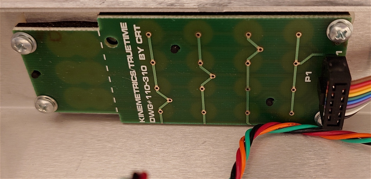
The system communicates its status and settings via a 2 x 16 character LCD and accepts input from a 19-key simple keyboard. The keyboard assembly is made by Kinemetrics / TrueTime. There is even a mention that the drawing (schematic diagram or printed circuit board layout) was done by CRT.
The LCD is made by Densitron, and model number is 4422BG-SNG.
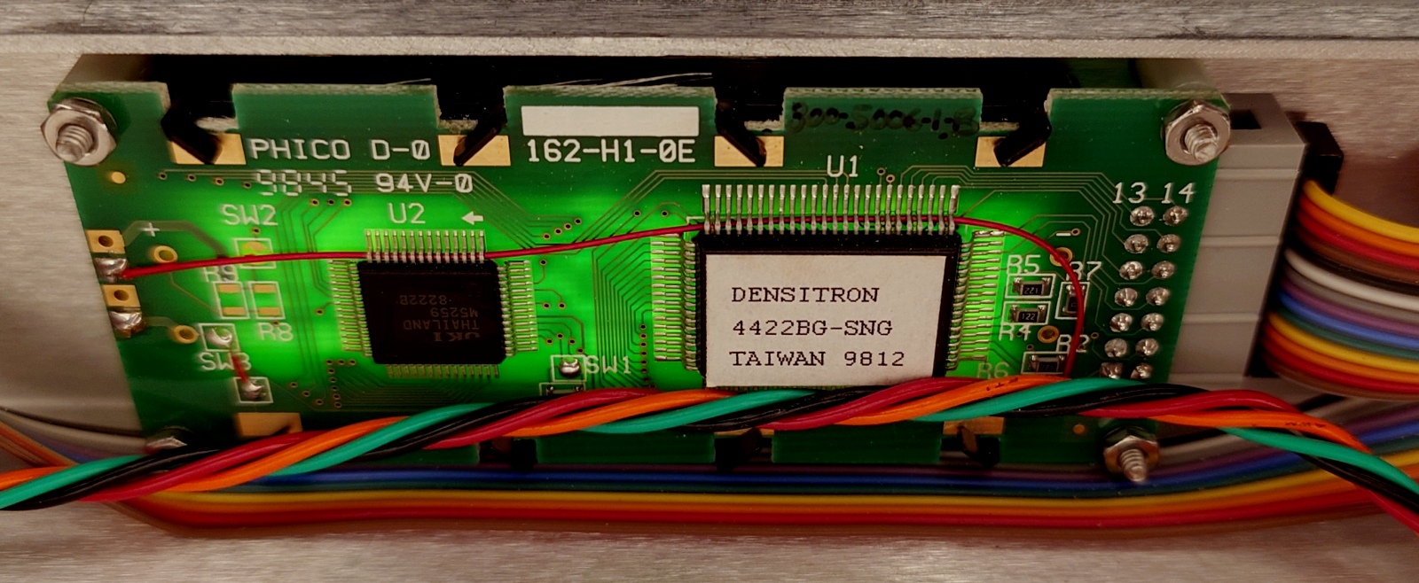
Although I have no means to verify this hypothesis, I think the LCD module is compatible with the Hitachi HD44780 interface. It's also interesting to note that the backlight is directly connected to the supply rail by means of a wire bodge. So there is no software-controlled LCD retro illumination. This means that a switch, or some sort of backlight control can be easily added, if needed.
Reflections
Judging by the sub-assemblies and components used in this system, it must've cost a small fortune back in those days. Now you can get one relatively cheap, provided you can find them. I think most of these units were scrapped once decommissioned. And those still in service, well, are still used.
Repair and Maintenance
The unit is in very good shape overall. And it was fairly clean, to begin with. I used a magic sponge and some cleaning solution to get the white-painted aluminum enclosure to an almost like-new condition. Every key on the frontal keypad works perfectly fine, the LCD is clean, and the backlight is bright. A bit too bright for nighttime. I might add a small circuit to control the backlight intensity via an external phototransistor. But that's a project for another time.
The NTS-100 time server is designed to be rack-mounted. Unfortunately, my networking rack is full, so I had to resort to a different location. I temporarily installed the unit on top of my left speaker.
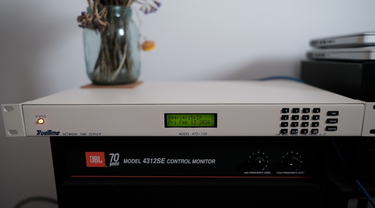
While it was functional, I initially observed that the top-right section of the enclosure gets really warm. But, as with all electronics, heat dissipation is normal to some extent. However, I should've asked myself why so much heat for a total of 15 W power rating? For sure, something was off course.
Servicing the Power Supply
The TrueTime NTS-100 unit is equipped with a switching mode power supply. The construction is straightforward, and it looks like a pretty standard PSU, built-to-order, and just integrated within the system. There is even a mention that the PCB was made in China. The rest of the PCBs inside the unit are clearly labelled either TrueTime, Trimble, or CRT, and appear to be of a better quality, on par with most other enterprise-class hardware of those times.
The good thing is that they used only quality components for the power supply. But even so, they are prone to aging issues. Judging by the various date codes, my unit was made in 1998, or possibly 1999. That makes it already 27 to 28 years old, at the moment I'm writing this article.
I started by measuring the output voltages. The power supply outputs +5 V and ±12 V and the voltages are stable and well within specifications. Directly, I ruled out the possibility of a bad power supply. But since I started with the PSU, let's continue with it.
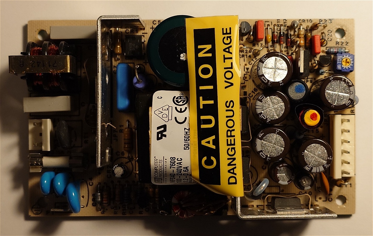
The first suspects in case of a SMPS malfunction are the electrolytic capacitors. There are only a few present in this design, and they all have date codes tracing back to 1998. I don't know how many hours this unit was operational, but it's safe to assume at least five years of 24/7 service. This means around 44,000 hours. I'd say that's well beyond specifications.
Thus, I removed all of the old electrolytic capacitors. I bet most of them are still in good working condition, but I will replace all of them as a form of preventative maintenance.
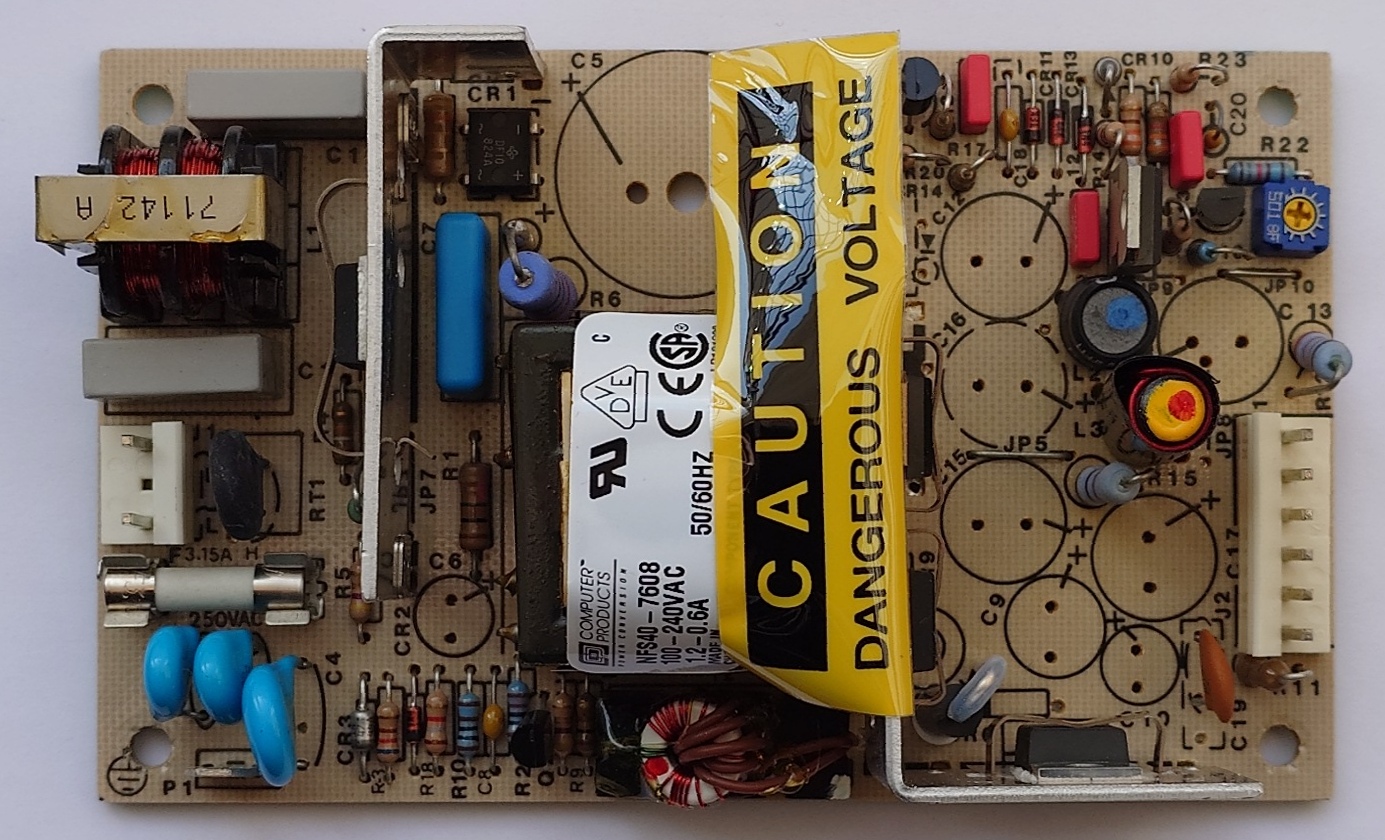
Next, I sourced new capacitors. This is the replacement list.
| TrueTime NTS-100 Power Supply | ||||
|---|---|---|---|---|
| Identifier | Value | Qty | Notes | Mouser Number |
| C5 | 100 uF / 400 V | 1 | Electrolytic Capacitor | 871-B43501B9107M |
| C6 | 22 uF / 50 V | 1 | Electrolytic Capacitor | 647-UBT1H220MPD8 |
| C9 | 100 uF / 35 V | 1 | Electrolytic Capacitor | 647-UHE1V101MPD |
| C10 | 10 uF / 50 V | 1 | Electrolytic Capacitor | 647-UBT1H100MPD8 |
| C12, C13 | 1000 uF / 35 V | 2 | Electrolytic Capacitor | 647-UHE1V102MHD |
| C15, C16, C17 | 2200 uF / 16 V | 3 | Electrolytic Capacitor | 647-UHW1C222MHD |
I replaced two 680 uF / 35 V capacitors with 1000 uF / 35 V, and three 1800 uF / 10 V capacitors with 2200 uF / 16 V. The new capacitors have a case diameter and length identical to the original parts. I went for the highest lifetime rating that I could find. As I couldn't find any 10 uF or 22 uF electrolytic capacitor with the required diameter and length with a lifespan in excess of 2,000 hours at rated operating temperature, I ordered aluminum organic polymer capacitors.
But eventually, I stumbled upon a stash of Nichicon BT series electrolytic capacitors that were leftovers from some other project. Conveniently, I found the required small values of 10 uF and 22 uF, both rated 50 V. These are a bit larger in diameter (8 mm), but the pin raster fits the PCB layout perfectly. I decided to re-purpose the two polymer capacitors that I already ordered, for something else. Thus, I used the BT series parts instead. These are rated for a maximum operating temperature of 125 °C, but there will be nowhere near that many degrees in this application.
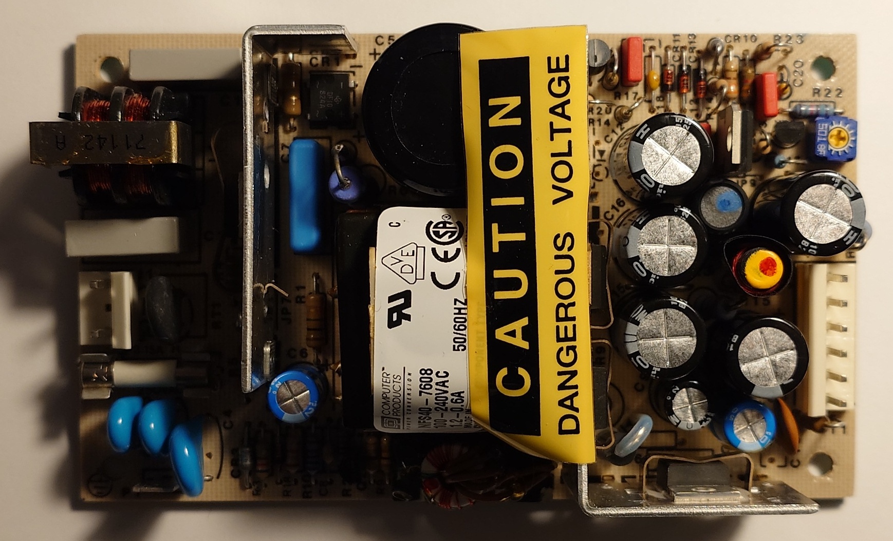
Let's examine the replacement capacitors from a different angle. I used a small piece of Kapton tape to cover a portion of the sleeve on C10, since it is too close to the heat sink. However, in practice it proved useless. The heat radiated is not enough to cause any damage to the sleeve, potentally exposing the aluminum can, even though there is half a milimeter space between the capacitor and the metal clip that secures VR1 to the heatsink.
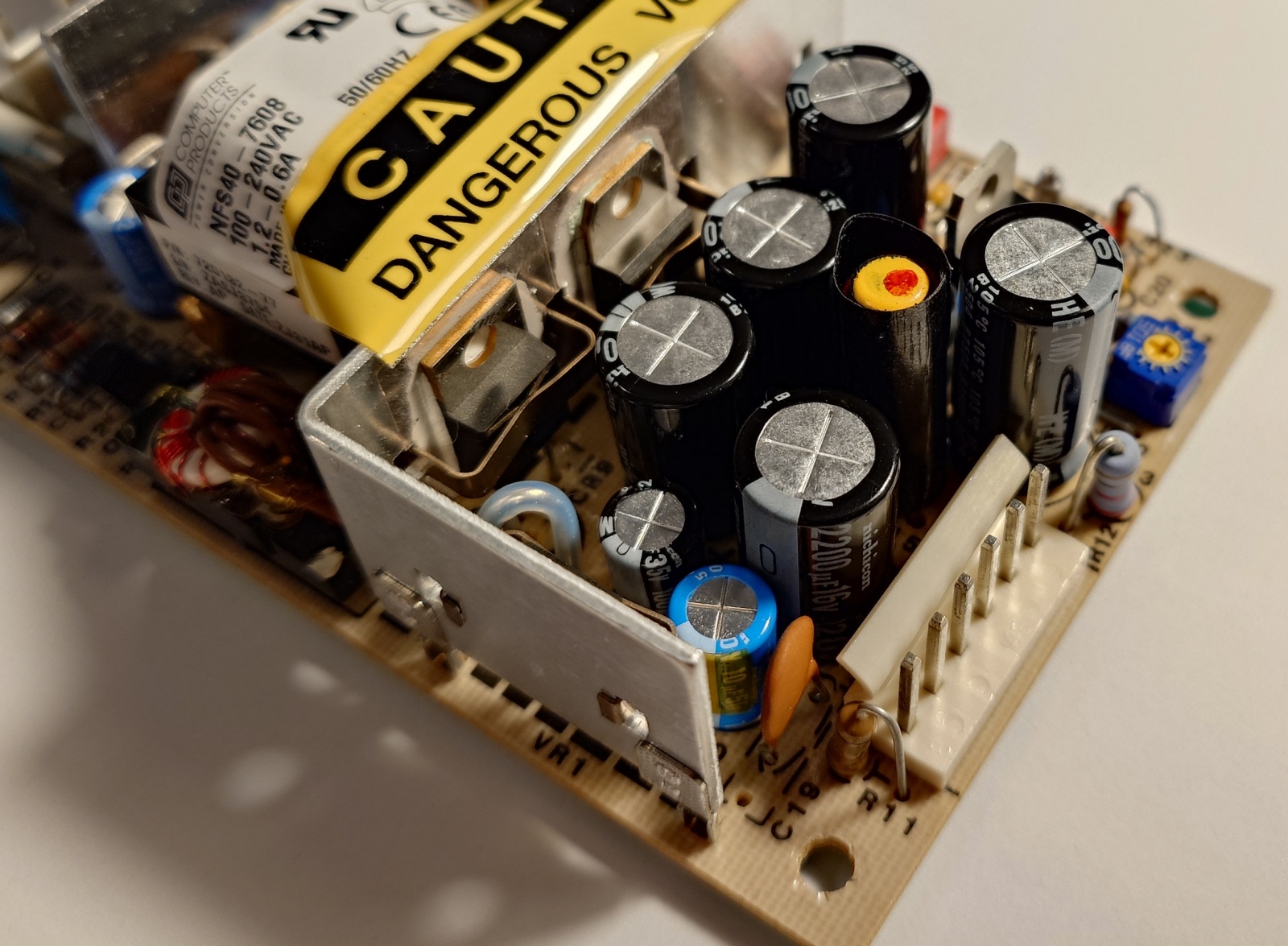
And the one in the vicinity of transistor Q1. C6 is indeed very close to the heat sink, but not as close as C10 discussed above.
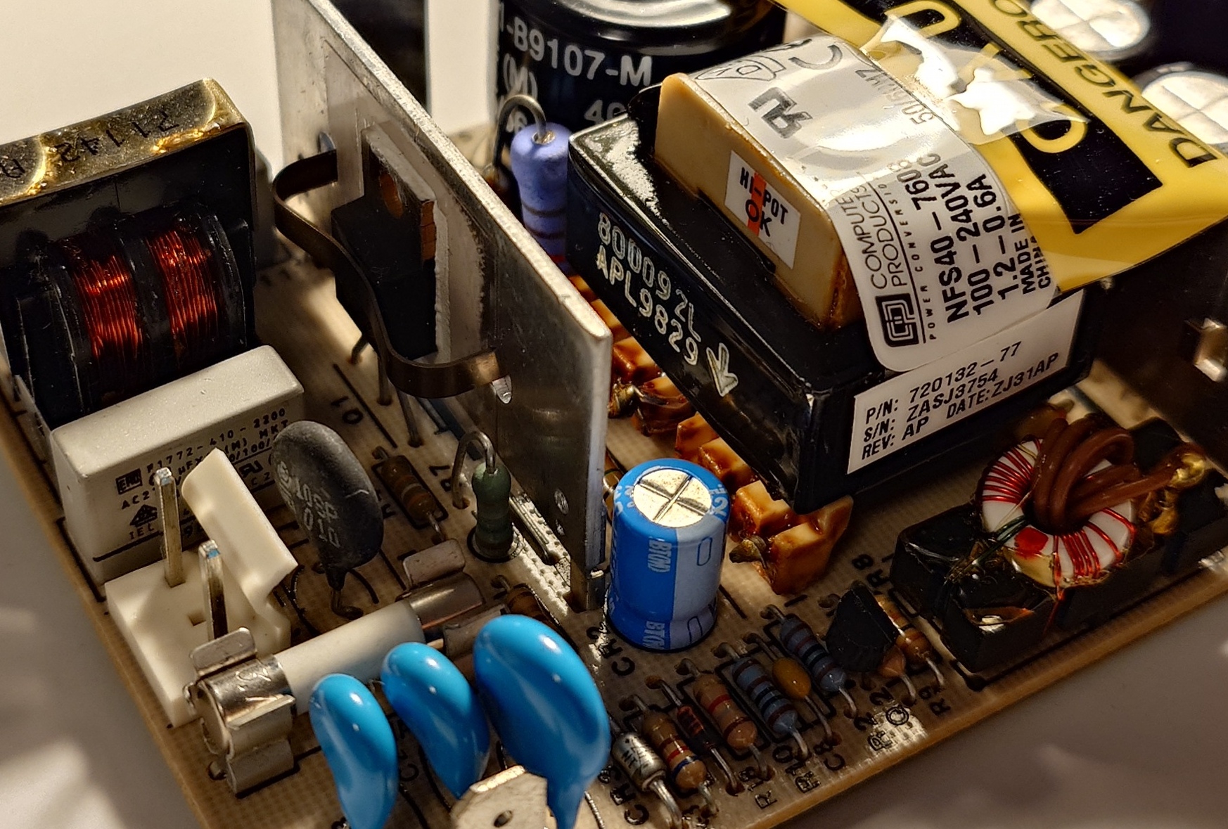
Now let's see the solder side.
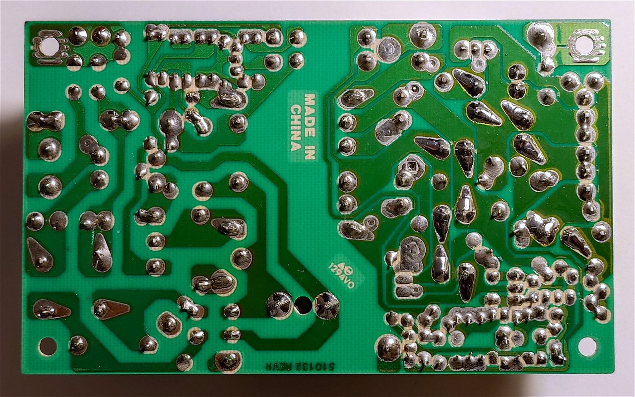
Replacement was straightforward as it's a joy to work on older, serviceable designs. Here are the old parts. I'm a bit suspicious as these capacitors feel very lightweight, but that does not always signify trouble.
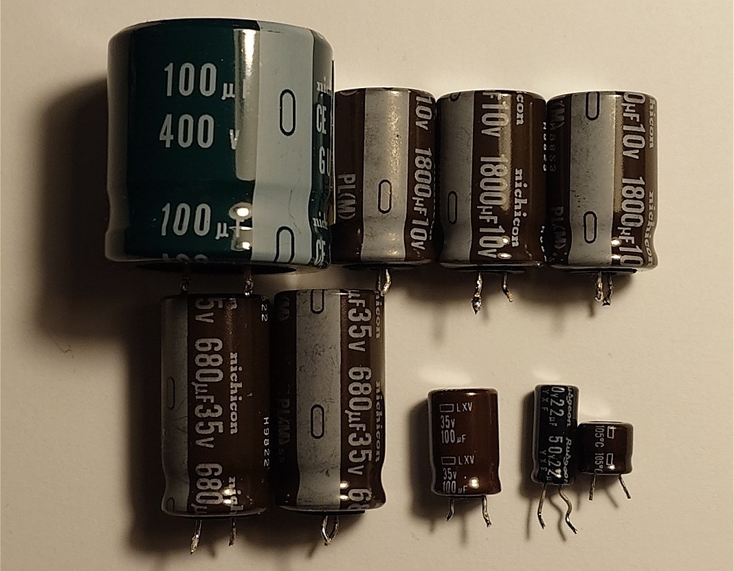
The old capacitors have the following parameters.
| CAPACITOR DATA | |||||
|---|---|---|---|---|---|
| Brand | Type | Style | Rating | Capacity | ESR |
| Nichicon | Electrolytic | Radial | 100 uF / 400 V | 91.20 uF | 1.12 Ω |
| Rubycon | Electrolytic | Radial | 22 uF / 50 V | 20.12 uF | 4.22 Ω |
| Chemi-Con | Electrolytic | Radial | 100 uF / 35 V | 91.20 uF | 1.56 Ω |
| Chemi-Con | Electrolytic | Radial | 10 uF / 50 V | 8.74 uF | 185.17 Ω |
| Nichicon | Electrolytic | Radial | 680 uF / 35 V | 648 uF | 0.10 Ω |
| Nichicon | Electrolytic | Radial | 680 uF / 35 V | 655 uF | 0.08 Ω |
| Nichicon | Electrolytic | Radial | 1800 uF / 10 V | 1800 uF | 0.09 Ω |
| Nichicon | Electrolytic | Radial | 1800 uF / 10 V | 1763 uF | 0.08 Ω |
| Nichicon | Electrolytic | Radial | 1800 uF / 10 V | 1804 uF | 0.10 Ω |
C10 is obviously dying. In addition, constantly measuring that capacitor for around 20 minutes, revealed a steady decrease of capacity to around 7 uF and an increase of ESR to around 250 Ω in an almost linear fashion. The rest of the capacitors appear to be still good.
But in any case, even with a faulty C10, the power supply was still operational and the work I carried out only made sure the PSU is future-proof. Finally, I reinstalled the PSU back in the unit.
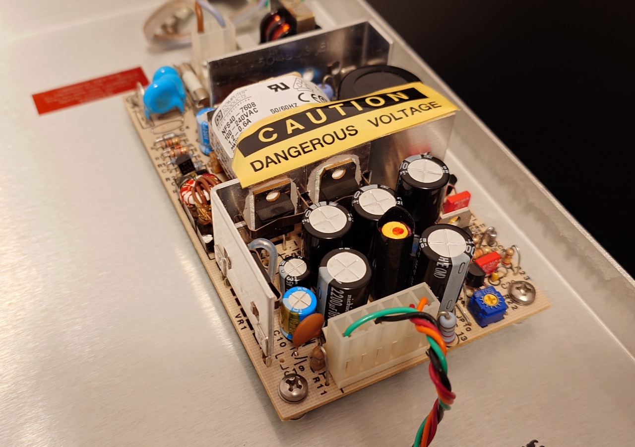
One thing is for sure, the heat sink on the main switching transistor (Q1) is insufficiently sized. It burns to the touch after just a few minutes of operation. I will have to find a way to extend it by attaching an extra sheet of aluminum.
Now let's dig deeper, and figure out the real root cause of malfunction.
Servicing the Computer Core
The brain of the Symmetricom TrueTime NTS-100 is an AMD branded 80C186 CPU. The entire computer is built on a single small form factor PCB. Simply looking at this PCB reveals a potential suspect. There is a large 100 uF / 20 V tantalum capacitor next to the power plug, near the CPU.
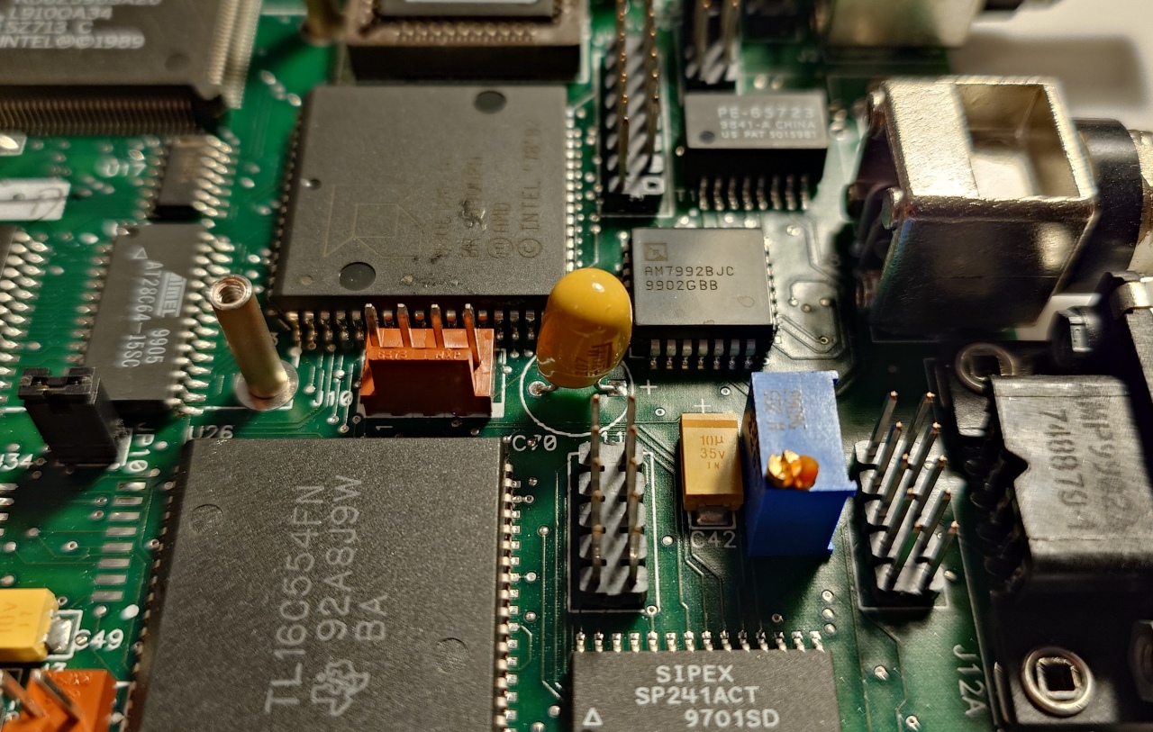
Without thinking too much, I connected the ohmmeter to the tantalum capacitor terminals. I was not very surprised to see a complete short-circuit. The instrument measured a perfect 0 Ω resistance across the supply rail and ground. To rule out any suspicion that an IC was shot, I carefully removed C70 and measured it independently of the circuit. The HP 4276A LCZ Meter clearly shows the capacitor is bad.
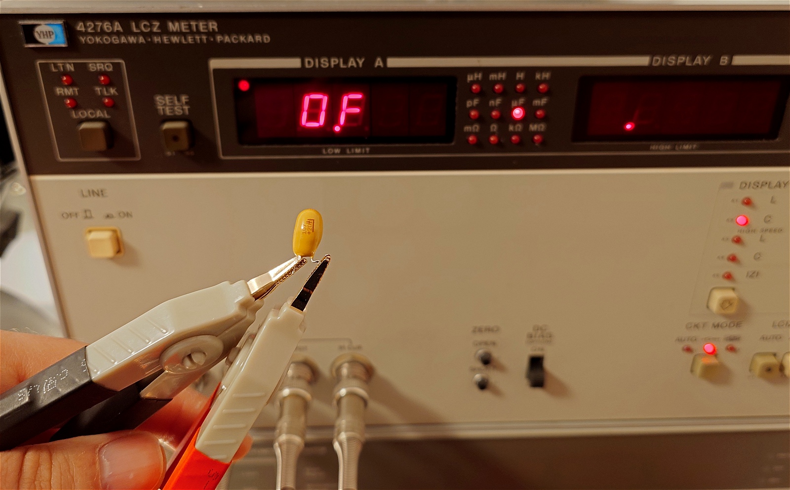
Old tantalum capacitors strike again! But what is most surprising is that this particular capacitor didn't burst in flames, nor did it crack, or release any smoke. A visual inspection shows a perfect epoxy coating without any visible cracks or tantalum-specific faults, such as holes caused by an explosion. In addition, the capacitor failed while the unit was in operation, which is even more puzzling, raising the question of why no smoke was released.
The following table lists the replacement capacitor.
| TrueTime NTS-100 Computer Core | ||||
|---|---|---|---|---|
| Identifier | Value | Qty | Notes | Mouser Number |
| C70 | 470 uF / 25 V | 1 | Polymer Capacitor | 80-A750MS477M1EAAE15 |
The only 100 uF tantalum capacitor that I found in my spare parts box was rated at 6 V, which is not good. Since C70 is a local power supply ripple filter capacitor, it can be replaced with any low-ESR capacitor with a capacitance equal or larger to 100 uF. I found in my spare parts box a Kemet aluminum organic polymer capacitor rated 470 uF / 25 V with the correct pin raster. It fits perfectly fine in place of the old tantalum capacitor and does a better job than the former part.
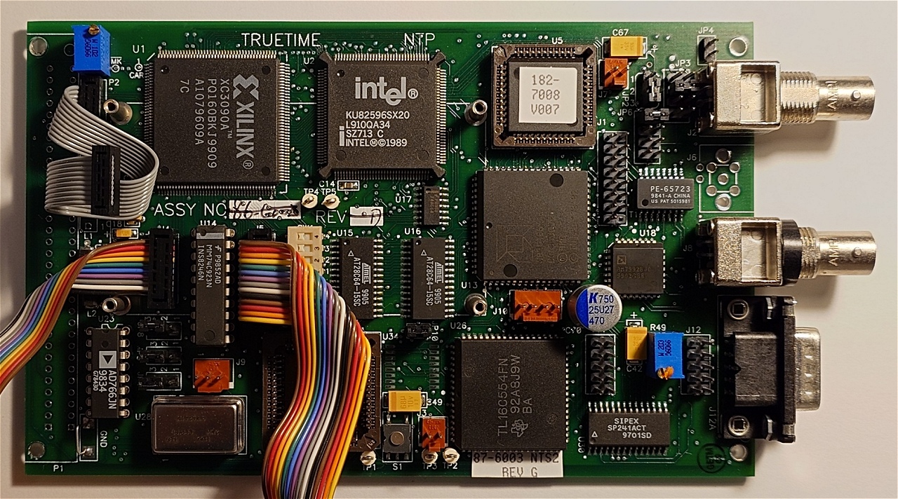
Here is a view from a different angle. There were some factory-left flux residues on the CPU which I cleaned prior to taking these pictures.
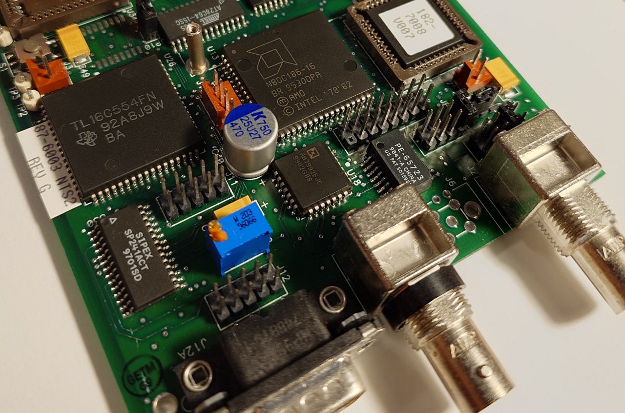
Sometimes I like to joke that this is Zen hardware debugging. The same concept that I sometimes apply to computer programming, when I mechanically employ self-taught patterns to solve various issues. It was the same in this case. I had a few bad experiences in the past with older tantalum capacitors from the 1980s and early 1990s.
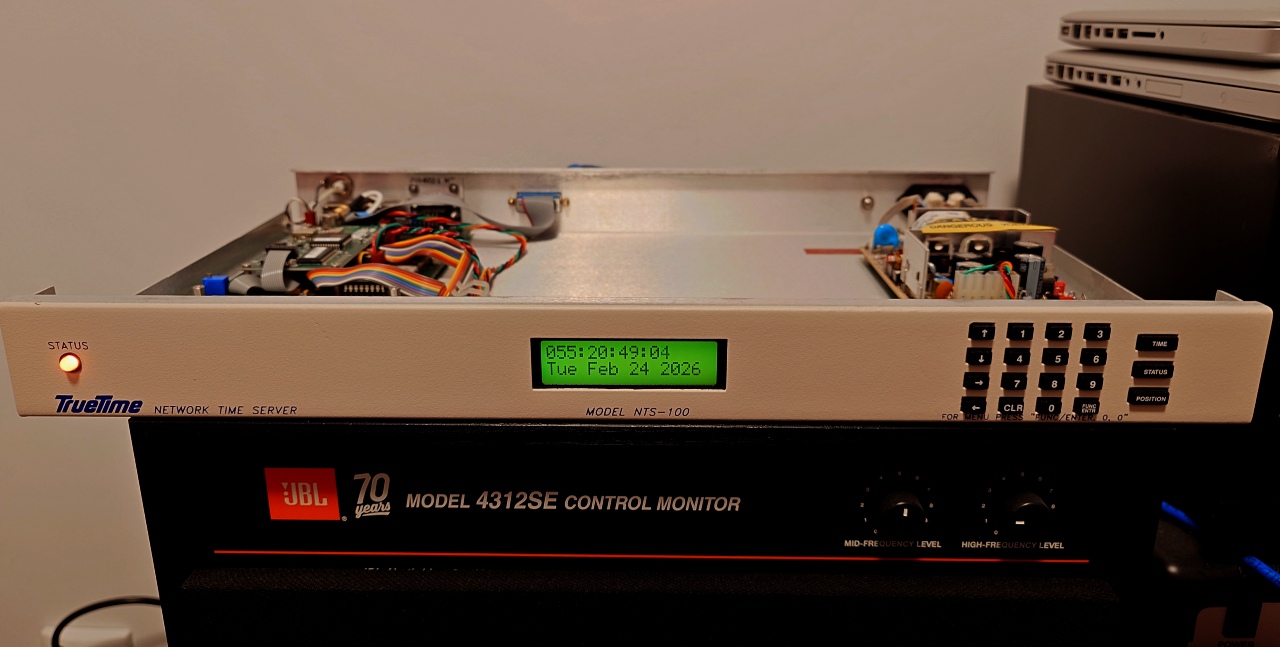
I reassembled the unit, connected all internal wires, and eager to check whether the issue was solved, I connected the NTP server to mains voltage. Unsurprisingly, it came back to life. It quickly acquired satellites and correctly began tracking the real-time data.
Future Plans
There is a lot of empty space in this 1u enclosure. As I said in the beginning of this article, I will have to think about a possible implementation of a PWM backlight LED driver, whose duty cycle is controlled by ambient light. Or maybe I'd keep things simple and build a classic (inefficient) linear dimming circuit with plain old transistors. However, I do have second thoughts about drilling a 5 mm hole in the front panel for the phototransistor. Anyway, that's food for thought.
For now, the initial issue is addressed, and the NTP server can go back to 24/7 service.
Curiosities
To connect one of these NTS-100 systems to a modern network, you need a MAU (media attachment unit), as its 10 Mbps network interface is based on an AUI (attachment unit interface) connector. If you're younger, chances are you have never heard of AUI or MAU. Think of the MAU as a modern media converter, but instead of fiberoptics to RJ-45, a MAU adapts AUI signaling to various other transmission signals over TP, thin or thick coaxial, and maybe other.

For this purpose, I use a readily available Allied Telesis CentreCOM 210T twisted pair transceiver MAU. I've never used AUI myself, so I was pretty excited to test this technology. Back in the late 1990s, I had an ISA network card with an AUI connector, but it was also equipped with RJ-45 and coaxial interfaces. I used RJ-45 from the start, effectively skipping the old networking standards.
Connecting the MAU is easy, and it has to be secured by the small sliding metal bracket available on the female socket. The POLARITY and POWER LEDs turned on instantly. Upon connecting the RJ-45 cable to the patch panel, the LINK LED also turned on. Unfortunately, it doesn't blink when data is transferred, so there is no visual activity feedback. But the MAU just works, and the NTS is visible on the network. Interestingly, the MAU runs a bit warm to the touch.
There is also a serial interface that can be used to perform the initial configuration of the system parameters. However, I preferred to do it from the keypad. I haven't tested the serial interface, yet, but I am eager to try it.
There are two other interesting outputs on the back of the unit. One is an alarm output that can be used to signal that there is a system error (i.e.: no GPS antenna cable is connected, or other faults), and the other one is a one pulse per second ACMOS level output signal, bound to BNC connector J2. This can be used to drive a precision clock circuit.
Some units are either equipped with an IRIG B 122 format time code output as standard (BNC connector J1), or a 10 MHz ACMOS level output. I didn't do any investigation on my unit to check what was present, but to be honest, I'd be glad if it had the 10 MHz frequency output. I could use that as a very precise frequency generator for my Hewlett-Packard 3325B Synthesizer/Function Generator. It already has an OCXO, but a GPS time-base is more stable. At least it doesn't require a consistent warm up period before being able to use the equipment.
Conclusions
I am glad there wasn't much to do to bring the unit back to life, as I'm passing through a harsh part of my life, when spare time is not really on my side. At some point, things will get back on track, and I'll have more time to dedicate to these kinds of projects.
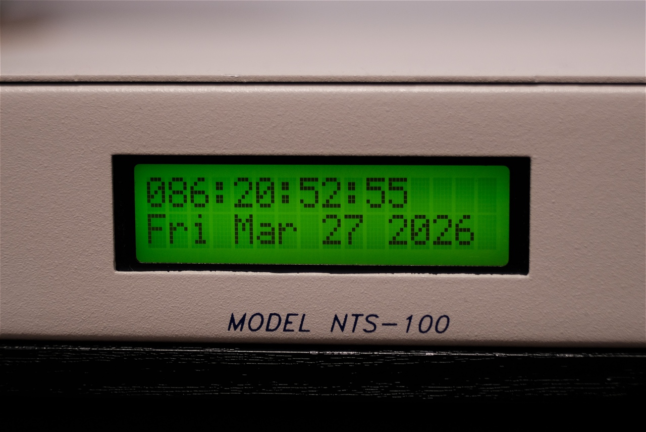
In addition, I really like the old days philosophy where things were built to last. A time when computing power was limited, and engineers were forced to squeeze as many CPU cycles as possible from what was available. For sure, these days, one could build a GPS-controlled NTP server with a Raspberry Pi, or maybe even a Raspberry Pi Zero, for an incredibly low power system. But being able to still use these old dinosaurs, way past their usable lifespan, is something that continues to intrigue me to this day.
I'm looking towards the next networking rack reconfiguration as I plan to permanently relocate the TrueTime NTS-100 network time server in the rack, where it should be. But for now, that's it.
Your Help Matters
This content is provided as-is and is not for commercial purposes. It reflects my experiments and research and should be treated as such. I release my work to the public for educational purposes. I did all this at my own expense and in my free time. So if you like my work, or find it useful or inspiring for your projects, please consider making a donation.
Copyright © 2004- Alexandru Groza
All rights reserved.
VER. 1.0 | REV. A