Article #3 | 02:10 PM Sunday 13/12/2020
Parts List
I have assembled a parts list for this amplifier. As always, my restoration touches almost all of the original transistors. I don't believe that transistors actually contribute to any specific sound signature.
The schematic value corresponds to what normally can be found in the electrical schematics. The recommended value is what I used as replacement for the former part. The BP inscription signifies a bipolar capacitor. Where I found appropriate, I have chosen a film capacitor replacement instead of an electrolytic. My reasons are reliability in time. Less electrolytic capacitors, less time-ticking bombs.
Descriptions and Parts Listings
There are two non-critical power resistors underneath the steel chassis. They are used for capacitor bleeding purposes and are soldered directly on each one of the two big power supply ripple filter capacitor terminals. Since they are of carbon composition which can drift in time, I decided to replace them in my unit.
|
|
| R001 | 3.3 kΩ / 2 W | 3.3 kΩ / 3 W | 71-CPF3-G-3.3K-E3 |
| R002 | 3.3 kΩ / 2 W | 3.3 kΩ / 3 W | 71-CPF3-G-3.3K-E3 |
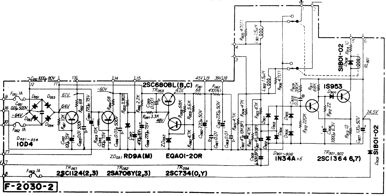
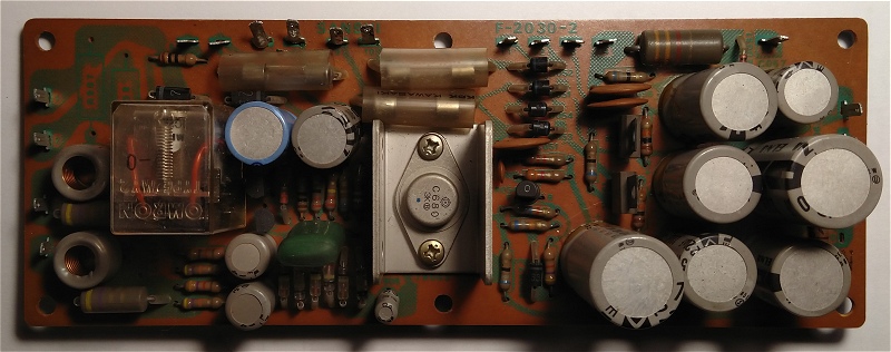
The Power Supply and Protector board is coded F-2030-1 and is located in the front-center of the amplifier, under the black metallic cage. You can quickly recognize it due to the big protector relay and stabilizer transistor cooled by a small U-shaped aluminum radiator.
|
|
| C052 | 100 uF / 75 V | 100 uF / 100 V | 647-UKZ2A101MHM |
| C054 | 220 uF / 75 V | 220 uF / 100 V | 647-UKZ2A221MHM |
| C055 | 100 uF / 75 V | 100 uF / 100 V | 647-UKZ2A101MHM |
| C057 | 470 uF / 16 V | 470 uF / 25 V | 647-UKZ1E471MHM |
| C058 | 220 uF / 75 V | 220 uF / 100 V | 647-UKZ2A221MHM |
| C060 | 220 uF / 50 V | | 647-UKZ1H221MHM |
| C062 | 220 uF / 50 V | | 647-UKZ1H221MHM |
| C901 | 47 uF / 10 V BP | 47 uF / 16 V BP | 647-UES1C470MPM |
| C902 | 47 uF / 10 V BP | 47 uF / 16 V BP | 647-UES1C470MPM |
| C906 | 1000 uF / 6.3 V | 1000 uF / 25 V | 647-UPW1E102MHD |
| C907 | 100 uF / 50 V | 100 uF / 100 V | 647-UPW2A101MHD |
| C908 | 1 uF / 50 V BP | 1 uF / 50 V FILM | N/A |
| R055 | 3.3 kΩ / 2 W | 3.3 kΩ / 3 W | 71-CPF3-G-3.3K-E3 |
| R905 | 4.7 Ω / 1 W | 4.7 Ω / 3 W | 71-CPF3-J-4.7-E3 |
| R906 | 4.7 Ω / 1 W | 4.7 Ω / 3 W | 71-CPF3-J-4.7-E3 |
| TR051 | 2SC1124 | KSC2690 | 512-KSC2690AYSTU |
| TR052 | 2SA706 | KSA1220 | 512-KSA1220AYS |
| TR054 | 2SC734 | KSC945 | 512-KSC945CGTA |
| TR901 | 2SC1364 | KSC945 | 512-KSC945CGTA |
| TR902 | 2SC1364 | KSC2383 | 512-KSC2383YTA |
| D051 | 10D-4 | 1N5395 | 625-1N5395-E3/54 |
| D052 | 10D-4 | 1N5395 | 625-1N5395-E3/54 |
| D053 | 10D-4 | 1N5395 | 625-1N5395-E3/54 |
| D054 | 10D-4 | 1N5395 | 625-1N5395-E3/54 |
| D907 | 1S953 | 1N4148 | 78-1N4148 |
| D908 | 10D-1 | 1N5392 | 625-1N5392-E3/54 |
| D909 | 10D-1 | 1N5392 | 625-1N5392-E3/54 |
| RL901 | DC24V MY-2 Relay | OMRON MY2-02-DC24 | 653-MY2-02DC24 |
There are two audio Driver boards in this amplifier. Each one of them is coded F-2029-1. They can be found symmetrically mounted near the big black power transistor aluminum radiators. These two boards are shielded by their respective black metallic cages. Keep in mind that from the table below, you need to double order each part.
|
|
| C801 | 2.2 uF / 50 V | 2.2 uF / 50 V BP | 647-UES1H2R2MDM |
| C807 | 47 uF / 10 V BP | 47 uF / 16 V BP | 647-UES1C470MPM |
| C815 | 47 uF / 80 V | 47 uF / 100 V | 647-UKZ2A470MHM |
| C817 | 47 uF / 80 V | 47 uF / 100 V | 647-UKZ2A470MHM |
| R825 | 8.2 kΩ / 0.5 W | 8.2 kΩ / 2 W | CPF28K2000JKE14 |
| R835 | 470 Ω / 0.5 W | 475 Ω / 1.75 W | 71-CMF704751%T1TR |
| R861 | 47 Ω / 0.5 W | 47.5 Ω / 1.75 W | 71-CMF7047R500FKBF |
| R863 | 47 Ω / 0.5 W | 47.5 Ω / 1.75 W | 71-CMF7047R500FKBF |
| R867 | 10 Ω / 0.5 W | 10 Ω / 1.5 W | 71-CMF6510R000FKEB |
| R869 | 10 Ω / 0.5 W | 10 Ω / 1.5 W | 71-CMF6510R000FKEB |
| R871 | 10 Ω / 0.5 W | 10 Ω / 1.5 W | 71-CMF6510R000FKEB |
| R873 | 10 Ω / 0.5 W | 10 Ω / 1.5 W | 71-CMF6510R000FKEB |
| R877 | 10 Ω / 2 W | 10 Ω / 1.5 W | 71-CMF6510R000FKEB |
| VR801 | 5 kΩ | | 652-3386H-1-502LF |
| VR803 | 200 Ω | | 652-3386H-1-201LF |
| TR801 | 2SA726 | KSA992 | 512-KSA992FTA |
| TR803 | 2SA726 | KSA992 | 512-KSA992FTA |
| TR805 | 2SC983 | KSC2383 | 512-KSC2383YTA |
| TR807 | 2SC983 | KSC2383 | 512-KSC2383YTA |
| TR809 | 2SC735 | BC337 | 512-BC33740TA |
| TR811 | 2SA562 | BC327 | 512-BC32740TA |
| TR813 | 2SC1124 | KSC2690 | 512-KSC2690AYSTU |
| TR815 | 2SA706 | KSA1220 | 512-KSA1220AYS |
| TR831 | 2SA706 | KSA1220 | 512-KSA1220AYS |
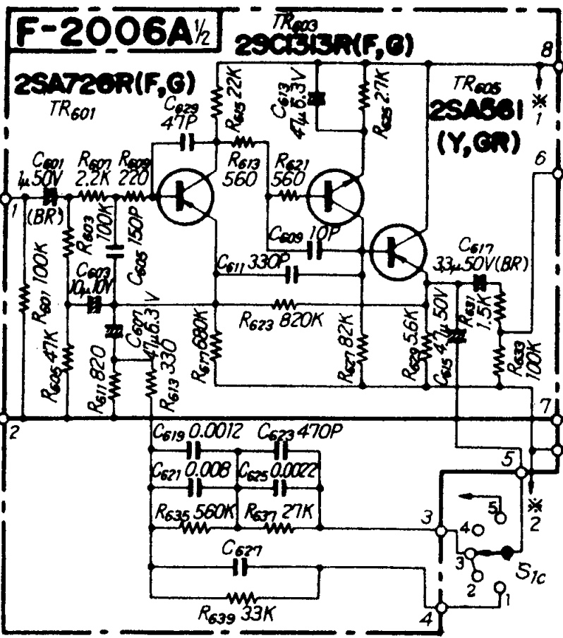
The Equalizer Block is coded F-2006A and implements the Phono preamplifier and the RIAA curve corrector. This board is left positioned, under the black metallic shield that also covers the Power Supply and Protector board. You can not miss it once you remove that heavy Faraday steel shield.
|
|
| C601 | 1 uF / 50 V | 1 uF / 50 V FILM | N/A |
| C602 | 1 uF / 50 V | 1 uF / 50 V FILM | N/A |
| C603 | 10 uF / 10 V | 10 uF / 16 V BP | 647-UES1C100MDM |
| C604 | 10 uF / 10 V | 10 uF / 16 V BP | 647-UES1C100MDM |
| C607 | 47 uF / 6.3 V | 47 uF / 16 V BP | 647-UES1C470MPM |
| C608 | 47 uF / 6.3 V | 47 uF / 16 V BP | 647-UES1C470MPM |
| C613 | 47 uF / 6.3 V | 47 uF / 16 V | 647-UFG1C470MEM |
| C614 | 47 uF / 6.3 V | 47 uF / 16 V | 647-UFG1C470MEM |
| C615 | 4.7 uF / 50 V | 4.7 uF / 50 V BP | 647-UES1H4R7MEM |
| C616 | 4.7 uF / 50 V | 4.7 uF / 50 V BP | 647-UES1H4R7MEM |
| C617 | 3.3 uF / 50 V | 3.3 uF / 50 V BP | 647-UES1H3R3MDM |
| C618 | 3.3 uF / 50 V | 3.3 uF / 50 V BP | 647-UES1H3R3MDM |
| TR601 | 2SA726 | KSA992 | 512-KSA992FTA |
| TR602 | 2SA726 | KSA992 | 512-KSA992FTA |
| TR603 | 2SC1313 | KSC1845 | 512-KSC1845FTA |
| TR604 | 2SC1313 | KSC1845 | 512-KSC1845FTA |
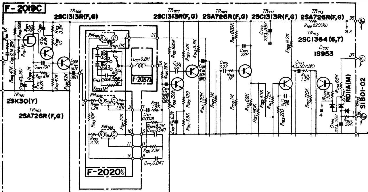
The Tone Control Block is coded F-2019C and is located beneath the steel chassis, under the Power Supply and Protector board. This board is the most complicated of them all as it contains a lot of electrolytic capacitors. I list them all below. Note that TC signifies a tantalum capacitor.
|
|
| C703 | 47 uF / 16 V | 47 uF / 25 V | 647-UPW1E470MDD |
| C704 | 47 uF / 16 V | 47 uF / 25 V | 647-UPW1E470MDD |
| C705 | 47 uF / 6.3 V | 47 uF / 25 V | 647-UPW1E470MDD |
| C706 | 47 uF / 6.3 V | 47 uF / 25 V | 647-UPW1E470MDD |
| C709 | 4.7 uF / 50 V | | 647-UES1H4R7MEM |
| C710 | 4.7 uF / 50 V | | 647-UES1H4R7MEM |
| C717 | 2.2 uF / 50 V | | 647-UFG1H2R2MDM |
| C718 | 2.2 uF / 50 V | | 647-UFG1H2R2MDM |
| C719 | 47 uF / 6.3 V | 47 uF / 25 V | 647-UPW1E470MDD |
| C720 | 47 uF / 6.3 V | 47 uF / 25 V | 647-UPW1E470MDD |
| C723 | 4.7 uF / 50 V | | 647-UES1H4R7MEM |
| C724 | 4.7 uF / 50 V | | 647-UES1H4R7MEM |
| C731 | 4.7 uF / 50 V | | 647-UES1H4R7MEM |
| C732 | 4.7 uF / 50 V | | 647-UES1H4R7MEM |
| C733 | 220 uF / 35 V | 220 uF / 50 V | 647-UKZ1H221MHM |
| C734 | 220 uF / 35 V | 220 uF / 50 V | 647-UKZ1H221MHM |
| C799 | 220 uF / 25 V | | 647-UKZ1E221MHM |
| TR701 | 2SK30 | | N/A |
| TR702 | 2SK30 | | N/A |
| TR703 | 2SA726 | KSA992 | 512-KSA992FTA |
| TR704 | 2SA726 | KSA992 | 512-KSA992FTA |
| TR705 | 2SC1313 | KSC1845 | 512-KSC1845FTA |
| TR706 | 2SC1313 | KSC1845 | 512-KSC1845FTA |
| TR707 | 2SC1313 | KSC1845 | 512-KSC1845FTA |
| TR708 | 2SC1313 | KSC1845 | 512-KSC1845FTA |
| TR709 | 2SA726 | KSA992 | 512-KSA992FTA |
| TR710 | 2SA726 | KSA992 | 512-KSA992FTA |
| TR711 | 2SC1313 | KSC1845 | 512-KSC1845FTA |
| TR712 | 2SC1313 | KSC1845 | 512-KSC1845FTA |
| TR713 | 2SA726 | KSA992 | 512-KSA992FTA |
| TR714 | 2SA726 | KSA992 | 512-KSA992FTA |
| TR715 | 2SC1364 | KSC1845 | 512-KSC945CGTA |
| TR716 | 2SC1364 | KSC1845 | 512-KSC945CGTA |
| D702 | 10D-1 | 1N5392 | 625-1N5392-E3/54 |
There is a fair amount of work to restore this amplifier. So I cannot but advice you to take your time and observe the electrical schematics and my capacitor lists. You can stick to the original values and types or you can follow my list. It is up to you. But the results will be similar. For best results, don't be shy to replace the small signal transistors. And especially those designated as 2SA726 and 2SC1313. Your amplifier will shine again and will produce that great Sansui sound. After all, this is another top performer and will surely reward your ears.
Tip
Should you venture into such a restoration, do not hurry, take your time and do the job once. And do it well.
Article #4 | 08:00 PM Monday 14/12/2020
Restoration
This amplifier is very similar to the AU-9500 both in terms of construction and servicing. Most of the recommendations and tips that I employed into the AU-9500 restoration, will also apply to this unit. Thankfully, mechanically is in good condition, which means that I don't have to search for any RCA arrays or any assorted mechanical parts.
General Considerations
Working on this unit exposes you to electrical hazards. There are lethal voltages inside.
Severe accidents and possibly death by electrocution might occur. I am qualified and skilled at electronics and I have been doing audio gear repairs for over 20 years. If you lack experience, please take these articles as just a knowledge base. Do not attempt to repair something that you cannot handle as there is a high chance of doing further damage while also possibly suffering accidents.
Good tools are a must for a quality restoration. I use eutectic soldering alloy and a temperature-controlled soldering station equipped with various tip shapes. I have both standard and precision desoldering pumps and desoldering wicks of various widths. To clean the flux, I use isopropyl alcohol and high-purity acetone.
Empirically, I found that soldering at a temperature of exactly 300 °C is safe for these vintage printed circuit boards. I have never lifted any pads and I never wait more than a couple of seconds with the hot tip on any pad. While working on the chassis, I use between 360 and 440 °C. Flux fumes are extremely toxic and should be avoided at all costs.
Every replacement part is brand new, from a reputable manufacturer, ordered from the U.S.A., Japan, or Germany. In addition, I only use parts that are suitable for specific circuit sections, after inspecting and comprehending the original schematic diagrams. Last but not least, I have years of experience backing up my choices and actions.
Sometimes, I like to take unnecessary actions, such as replacing perfectly working components for futureproofing, or completely stripping down PCBs of parts for a better cleaning. While tedious, I have fun while doing so, and I also learn a thing or two in the process.
Power Supply / Chassis Restoration
On the chassis there are two really large filtering capacitors. I have tested these against the specifications and they are doing fine. So no replacement for these yet. On the other side, I have decided to replace the two capacitor bleeding resistors with modern DALE resistors rated 3.3 kΩ / 3 W.
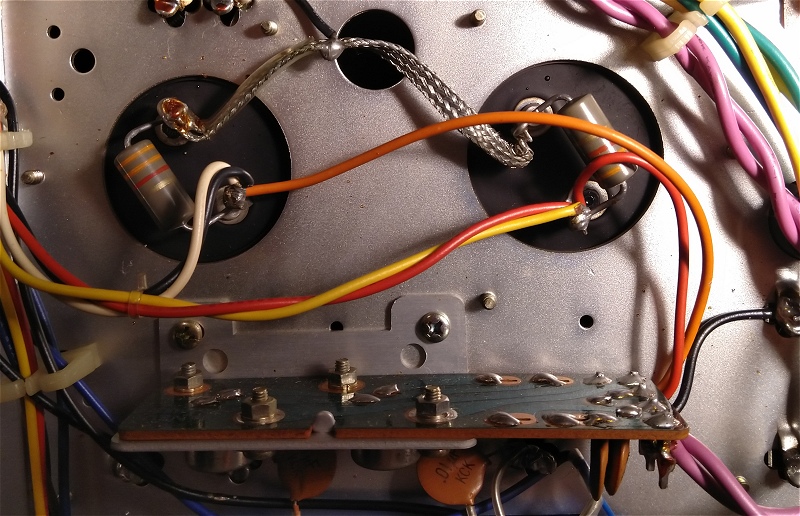
Unfortunately I forgot to take pictures of the replacement parts.
F-2030-1 Power Supply / Protector Board Restoration
This board is really easy to remove but you need to note the order of the wires that are attached to it. Besides four soldered wires, all the other wires are using connectors. The four heavy duty power wires which are soldered are kind of hard to desolder even using a vacuum pump. Why is that? Because unlike the AU-9500 that I previously serviced, here the wires were looped inside the metal post holes. I edend up cutting small pieces of the loops so that I can safely remove the wires.
Beware that this board has very large ground planes so soldering and desoldering capacitors is difficult to impossible for a low power soldering tool. So good tools and a lot of precaution is necessary for a clean job.
The board prior to the restoration.
In a similar manner, everything has to go off so that I can clean the PCB and ditch the junk parts.
Dreadful Sansui glue.

There's a lot of work for me on this PCB.
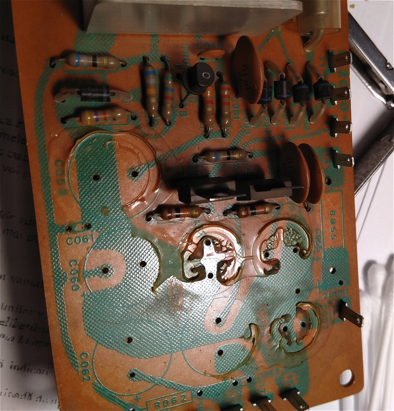
Using high purity technical acetone -- dangerous for the lungs, by the way, good ventilation required -- I managed to remove the glue within about 30 minutes.

I used Nichicon MUSE KZ series capacitor replacements for the old ELNA ones. These capacitors even have the same dimensions as the original parts. So I changed the two 220 uF / 75 V capacitors with 220 uF / 100 V capacitors. Then I changed the two 100 uF / 75 V capacitors with 100 uF / 100 V parts. C057 was rated at 470 uF / 16 V. The replacement is 470 uF / 25 V. Regarding the replacements for C060 and C062, I have used the same 220 uF / 50 V rating for both of them. C907 is used as filter for the protector circuit. It was originally rated at 100 uF / 50 V. I replaced it with a Nichicon PW series part rated 100 uF / 100 V. In the protection circuit, C901 and C902 were bipolar capacitors, originally rated at 47 uF / 10 V. I replaced both of them with Nichicon ES series 47 uF / 16 V bipolar parts. C908 is a 1 uF / 50 V bipolar capacitor. I have replaced it with a Panasonic stacked film part of the same rating. C906 is part of the relay delay circuit and was originally rated at 1000 uF / 6.3 V. My replacement is a Nichicon PW series part rated at 1000 uF / 25 V.
In terms of semiconductors, I have replaced 2SC1124 with KSC2690 (TR051), 2SA706 with KSA1220 (TR052), 2SC734 with KSC945 (TR054), and 2SC1364 with KSC945 (TR901). Originally TR902 was also a 2SC1364 but I opted for a more robust KSC2383 as replacement. Diodes D051, D052, D053, and D054 were originally 10D-4 and were replaced with 1N5395. All other 10D-1 diodes (D908 and D909) were replaced with 1N5392. In addition, I have replaced the 1S953 (D907) with 1N4148.
I have replaced the power resistors with DALE parts. Thus, R055 was 3.3 kΩ / 2 W and I have replaced it with 3.3 kΩ / 3 W. Similarly R905 and R906, originally 4.7 Ω / 1 W were replaced with 4.7 Ω / 3 W metal film resistors.
The relay was replaced with a new OMRON MY2-02-DC24 part.
Halfway through.
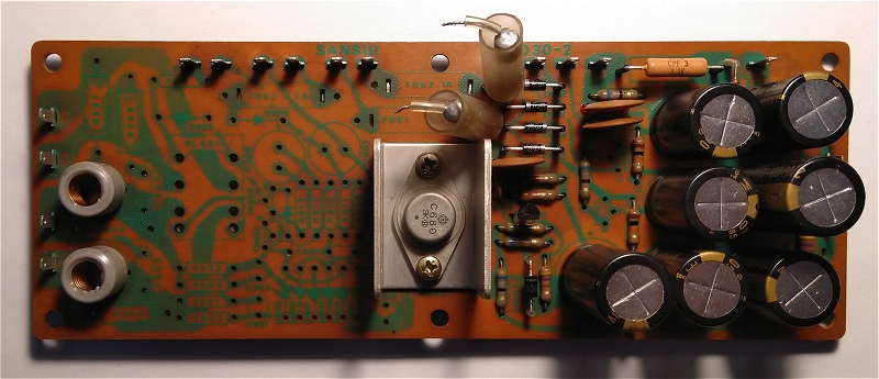
PCB side cleaning. I always loved these old Sansui layouts.

The board after the job. Click the picture to enlarge it.

I have used glass spacers wherever I found appropriate.

Details.

More details.

Solder side looks great now.
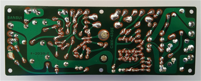
That's it for this board.
F-2029 Driver Board Restoration
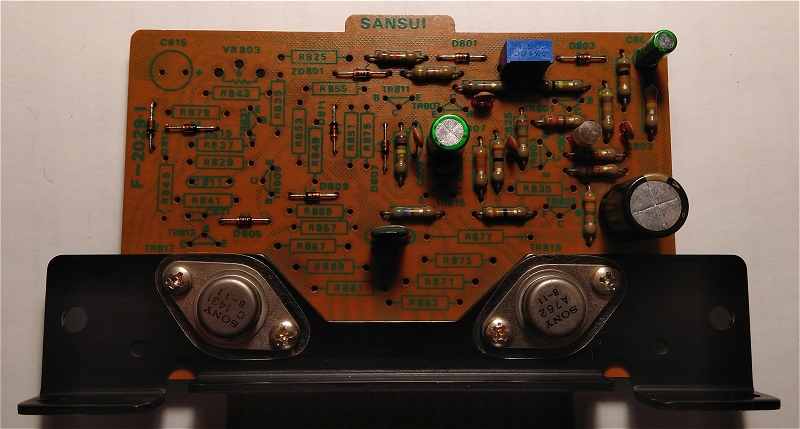
These two power amplifier sections are the easiest printed circuit boards to work on of them all. There are only four capacitors and two transistors to change per board. There is also a thermal fuse glued on top of a small signal transistor. If you want you can take care of removing that one too. I did as there is no apparent need for a thermal fuse in this part of the circuit. Furthermore some of these amplifiers come from the factory without thermal fuses.

Here is the left channel board prior to refurbishing.

The largely unnecessary thermal fuse is seen glued on a small signal transistor.

I divided the PCB in two and took off all parts from the right section. Then I cleaned everything with isopropyl alcohol.
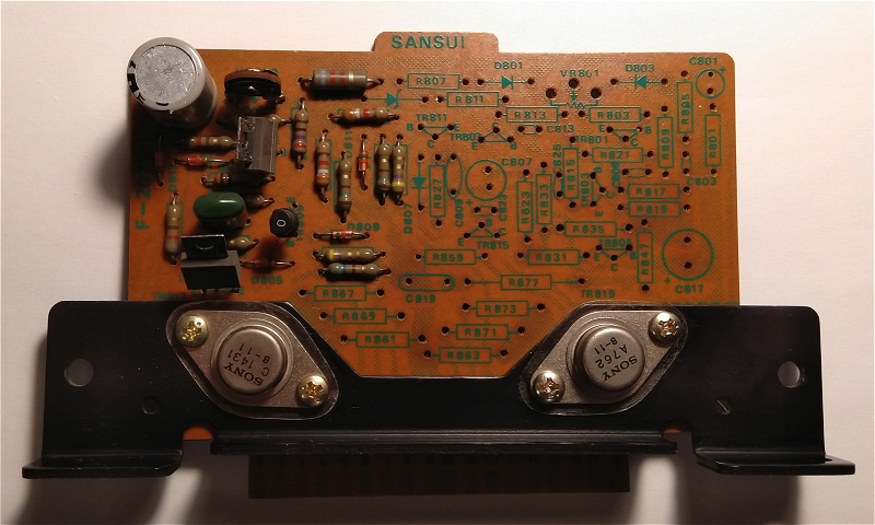
Including the bottom side. No more old flux residues.
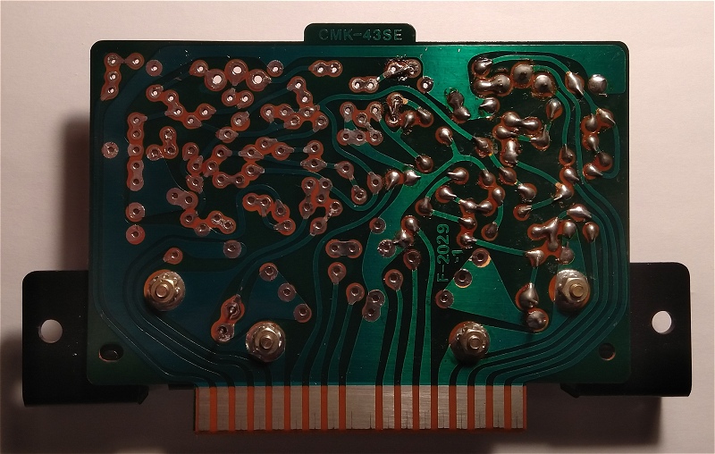
I rebuilt the rightmost section and took every part off from the leftmost section. Then I applied the same cleaning treatment.

On the solder side I cleaned the PCB well. All good and as usual, no lifted pads.

...
...
...
Now comes the right channel board assembly.

As before, I took off all parts and cleaned everything.

Same cleaning treatment was applied on the soldering side.

The card looks alright, no lifted pads.

Then I started to rebuild it.
...
...
...
F-2006A Equalizer Board Restoration
Removal of the board is extremely simple. The procedure is to first remove the two side screws holding the steel Faraday cage. The the cage itself. After that you gently pull the board upright out of its socket.
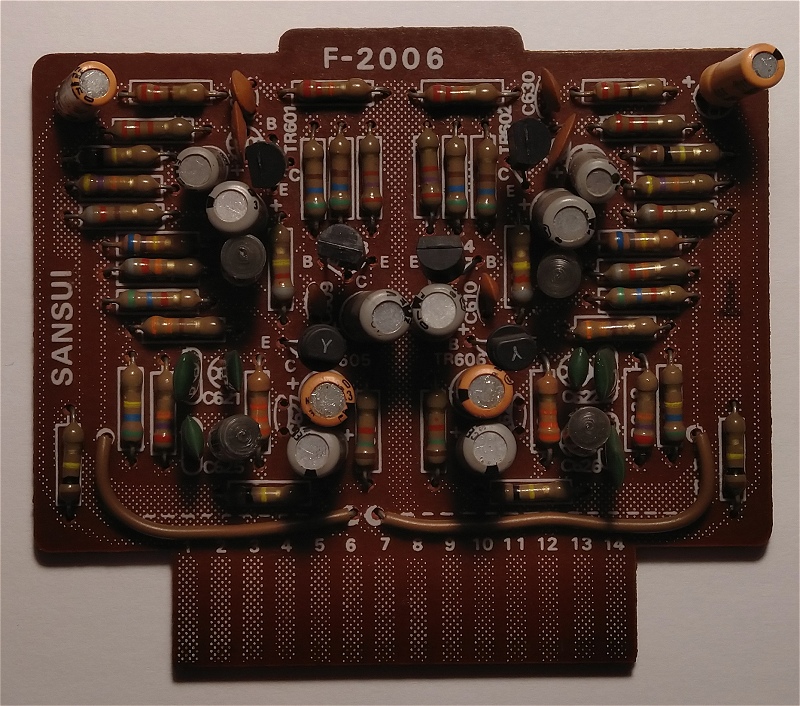
Working on this board is easy as well. There are a twelve capacitors six transistors to change. The PCB is identical to those found in Sansui AU-9500 units.
This is the board before restoration.
C601 and C602 are the input stage coupling capacitors. Originally they were 1 uF / 50 V, electrolytic. I have changed them with 1 uF / 50 V Panasonic stacked film capacitors. C603 and C604 which were originally 10 uF / 10 V were replaced with 10 uF / 16 V Nichicon ES series bipolar capacitors. C607 and C608, originally 47 uF / 6.3 V were replaced with 47 uF / 16 V Nichicon ES series bipolar counterparts. C613 and C614 are used to stabilize the static functioning point of two transistors and were originally rated at 47 uF / 6.3 V. I have used 47 uF / 16 V Nichicon FG series replacements. C615 and C616 are part of the RIAA correction network and originally were 4.7 uF / 50 V. I have replaced them with 4.7 uF / 50 V Nichicon ES series bipolar parts. The output coupling stage capacitors, originally rated at 3.3 uF / 50 V were replaced with 3.3 uF / 50 V Nichicon ES series bipolar capacitors.
Parts removed from one channel.

Details on the printed circuit board.
Halfway through.

And after.

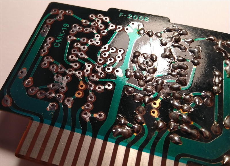
On the back side I have renewed the solder joints.

F-2019C Tone Control Board Restoration
Removal of the board is extremely difficult. The procedure involves removing of the power supply board. Then the metallic shielding cage. After you have access to the solder side of the board which is bolted to the chassis with six screws. There is another fixing point in the left side, near the local filtering capacitors. This one requires a powerful soldering iron to detach. But this is not all. There are also a whole lot of wires attached to the solder side of this board. So I decided to let this board alone and adopt a different approach. I have positioned the amplifier so that I can easily reach the components from beneath, while having enough space to work on the solder side. It is an awkward job but the wires were untouched.
This is the board before restoration.
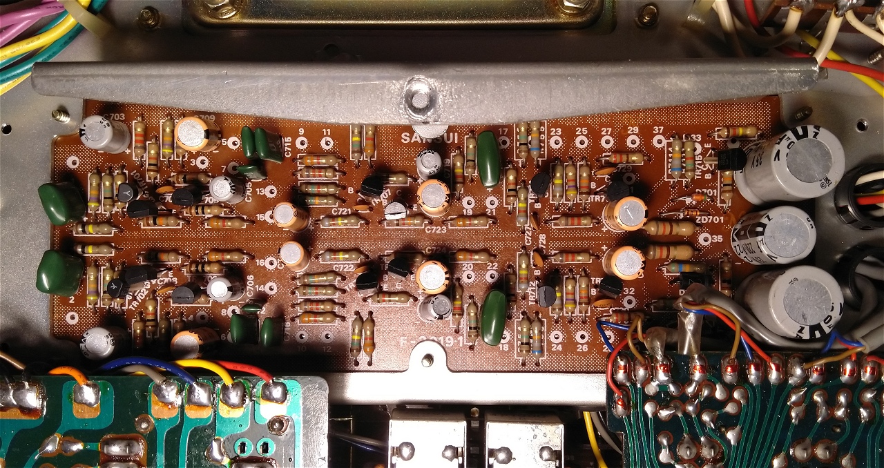
The local emitter decoupling capacitors C703, C704 were 47 uF / 16 V and C705, C706, C719, C720 were rated 47 uF / 6.3 V. I have used Nichicon PW series replacements rated 47 uF / 25 V for all of them. Stage coupling capacitors C709, C710, C723, C724, C731, C732 were rated 4.7 uF / 50 V. Nichicon ES series bipolar parts rated 4.7 uF / 50 V were used as replacement. I have used the same ES bipolar series for C717, C718, but rated 2.2 uF / 50 V stage coupling capacitors. The local filtering capacitors C733 and C734 were 220 uF / 35 V. I have used Nichicon MUSE KZ series capacitors rated 220 uF / 50 V. The same for C799, originally 220 uF / 25 V, now replaced with new MUSE KZ series part of the same rating.
There are a also six 2SA726 and six 2SC1313 transistors to change on this board. I have used hFE matched pairs as before. In my unit the first preamplifier stage was very noisy. It is constructed around two 2SK30 FET transistors. I have used NOS Toshiba 2SK30Y replacements. There are also two 2SC1364 transistors on this board. I have replaced these with KSC945 transistors which apparently work very well in this circuit.

This board concludes the replacement of parts in this audio amplifier.
Aftermath
Old parts.

This is everything that I did on this amplifier.
